Method for producing high-strength components by means of adiabatic blanking

A technology for parts and workpieces, applied in the field of producing high-strength parts by adiabatic stamping, to achieve the effects of simple production, high efficiency and easy flow

Active Publication Date: 2012-10-24
ADIENT LUXEMBOURG HLDG SARL
View PDF7 Cites 3 Cited by
  • Summary
  • Abstract
  • Description
  • Claims
  • Application Information

AI Technical Summary

Problems solved by technology

A disadvantage of the known methods and devices is that after the stamping operation rework must be carried out, for example hardening of the surface of the component in order to produce a high-strength component

Method used


Image

  • Method for producing high-strength components by means of adiabatic blanking
  • Method for producing high-strength components by means of adiabatic blanking
  • Method for producing high-strength components by means of adiabatic blanking

Examples


Embodiment Construction

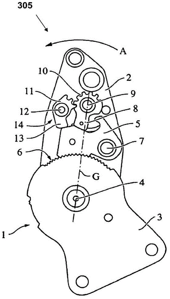
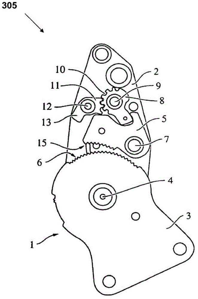
[0020] figure 1 A blocking and tilt adjustment device with a latching pawl according to the invention is shown schematically. The fitting 1 consists of a first fitting part 2 and a second fitting part 3 which are rotatable with respect to each other about a rotation axis 4 . The second fitting part 3 is for example arranged on the seat part and the fitting part 2 is arranged on the backrest of the vehicle seat, or vice versa. The locking takes place by engaging the mating teeth 15 of the latching pawl 5 into the teeth 6 of the second fitting part 3 . The latching pawl 5 is arranged on the fitting part 2 so as to be rotatable about the axis 7 and is clamped in the tooth 6 by the blocking cam 8 and fixed in this position. The blocking cam 8 , which rests on the periphery of the latching pawl 5 , rotates relative to the fitting part 2 about the axis of rotation 9 and meshes with a pinion 11 , via partial peripheral teeth 10 , which has a direction along the latching pawl 5 . T...


PUM

PropertyMeasurementUnit
thicknessaaaaaaaaaa

Abstract

The present invention relates to a method for producing a component of an adjustment device for vehicle seats, wherein, in a first step, a work piece is machined such that the work piece is harder in a first region than in a second region, and / or in that the work piece is of a larger geometrical size in a third region than in a fourth region, wherein, in a second step, the work piece is deformed in such a way that a tool is moved onto the work piece at a speed greater than 1 m / s.

Description

technical field [0001] The invention relates to a method of producing a component of an adjustment device for a vehicle seat, wherein in a first step the workpiece is machined such that it is harder in a first region than a second region and / or such that the workpiece is harder in a third region The zone has a larger geometry than the fourth zone, wherein in the second step the workpiece is shaped by moving the tool onto the workpiece at a speed greater than 1 m / s. Background technique [0002] Methods of producing parts are well known. Furthermore, documents EP 1 516 717 A1, WO 2007 / 026091 A1 and WO 2007 / 026090 A1 disclose methods and devices using the principle of adiabatic separation. In the principle of adiabatic separation, the tool is moved at high speed onto the workpiece to punch out the part as the heat develops at the edge of the separation. A disadvantage of the known methods and devices is that after the stamping operation, further processing, eg hardening of t...

Claims


Application Information

Patent Timeline
Patent Type & Authority Applications(China)
IPC IPC(8): B60N2/22B21D28/16B21D53/88B23P15/14B21D28/00B60N2/235B21D53/28
CPCB21D53/88F16H55/06B21D53/28B21D28/00B21D35/006B21D22/02B21D28/16B21B1/00B60N2/2352Y10T74/19884B23P15/14B60N2/22
Inventor H-G·韦纳B·格罗斯
Owner ADIENT LUXEMBOURG HLDG SARL
Why Eureka
Try Eureka