Roof structure, fixture for solar cell module, and method for installing solar cell module

A technology for solar cells and installation tools, which is applied to the support structure of photovoltaic modules, photovoltaic modules, building structures, etc., and can solve problems such as cracks, lack of tiles, and screws that cannot function

Active Publication Date: 2014-12-10
KANEKA CORP
View PDF8 Cites 0 Cited by
  • Summary
  • Abstract
  • Description
  • Claims
  • Application Information

AI Technical Summary

Problems solved by technology

[0022] In prior art roof construction, if two screws or nails penetrate the same slate tile and cause the tile to be chipped or cracked, all the screws securing the mounting become non-functional

Method used


Image

  • Roof structure, fixture for solar cell module, and method for installing solar cell module
  • Roof structure, fixture for solar cell module, and method for installing solar cell module
  • Roof structure, fixture for solar cell module, and method for installing solar cell module

Examples


Embodiment Construction

[0162] Embodiments of the present invention will be further described below.

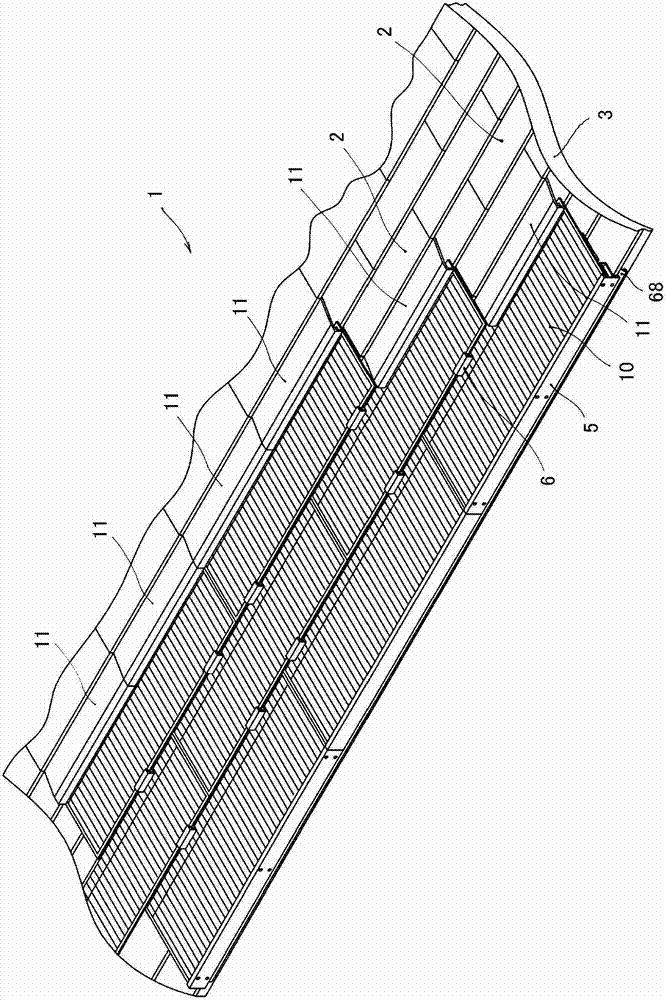
[0163] Such as figure 1 As shown, the roof structure 1 of this embodiment is formed on a basic roof structure 3 paved with slate tiles (roof components) 2 via an eaves end mounting part (eaves end mounting tool) 5 and an intermediate mounting part (installation tool) 6 The structure in which the solar cell module 10 is mounted. Moreover, the flashing 11 is partially provided in the necessary part.

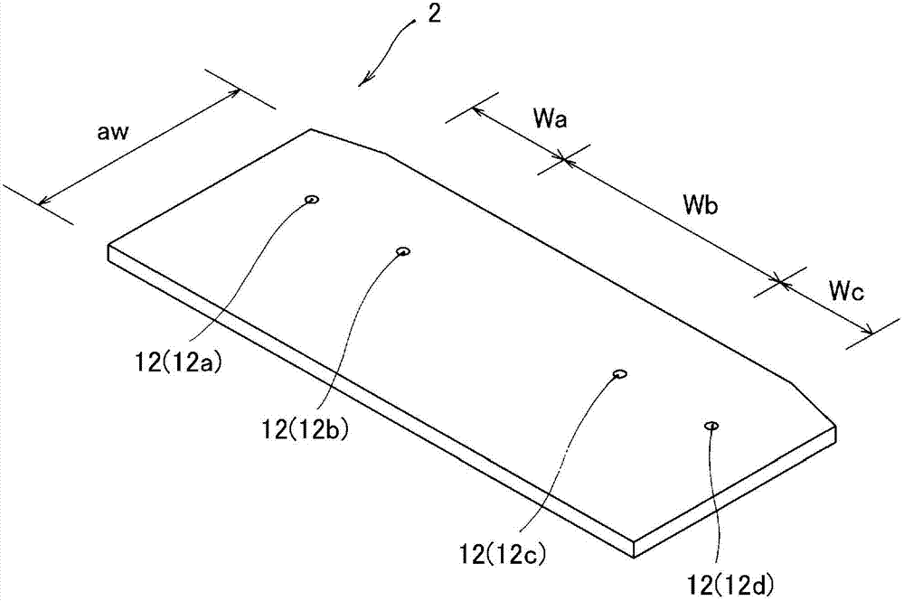
[0164] Such as figure 2 As shown, the slate tile 2 is an approximately rectangular thin plate formed from cement or the like. Near the center of the slate tile 2 in the short side direction, four mounting holes 12 are provided in advance in one row. In the present embodiment, the intervals between the attachment holes 12 are uneven, and the intervals between the two central holes 12b and 12c are larger than the intervals between the other holes.

[0165] In detail, if the four holes are hole 12a, h...


PUM


Abstract

It is an object to develop a roof structure having a high water interception, being safe from leaking of rain, and ensuring a certain level of mounting strength even in breaking of one piece of roof members. Solar cell modules (10) are mounted on a fundamental roof structure (3) with slate tiles (roof member) (2) via eaves-side mounting brackets (eaves-side clamps) (5) and intermediate mounting brackets (clamps) (6). The intermediate mounting brackets (6) each are attached to an end portion of a "specific roof member" so that a lower plate (72) is positioned between the "specific roof member" and an "underlying roof member". The lower plate (72) is fixed by a screw or the like driven in a hole (100). The "specific roof member" is arranged over the "underlying roof member" in which the screw is driven, thereby protecting an attaching hole (12) from rainwater seepage. An upper plate 73 overlaps the "specific roof member" with a fastening element (117, 118, 119) driven in the attaching hole (12). An "overlying roof member" is arranged over the "specific roof member", thereby also protecting the attaching hole (12) from rainwater seepage.

Description

technical field [0001] The present invention relates to a roof structure on which solar cell modules are mounted. The present invention also relates to an installation tool used to realize the above-mentioned roof structure and an installation method for installing a solar cell module on a roof. Background technique [0002] A solar battery module is a device that integrates a solar panel, terminals and other accessories, and can receive sunlight to generate electricity. [0003] In recent years, the number of households using photovoltaic power generation systems in which solar cell modules are installed on the roofs of general households and electricity used in the households is supplied by electricity generated by the solar cell modules has been increasing. [0004] Here, as a method of installing a solar cell module on a roof of a general household, there are a structure in which a solar cell module functioning as a tile (roof member) is laid on a roof base, and a struc...

Claims


Application Information

Patent Timeline
Patent Type & Authority Patents(China)
IPC IPC(8): E04D13/18E04D1/30H02S20/23
CPCH02S20/23Y02E10/50H01L31/046Y02B10/12Y02B10/10
Inventor 石田谦介
Owner KANEKA CORP
Why Eureka
Try Eureka