Transmission control device, memory control device, and plc provided with the transmission control device

A transmission control and memory technology, applied in the field of PLC, to ensure the simultaneity, prevent access conflicts, and shorten the standby time.

Inactive Publication Date: 2012-10-24
MITSUBISHI ELECTRIC CORP
View PDF4 Cites 6 Cited by
  • Summary
  • Abstract
  • Description
  • Claims
  • Application Information

AI Technical Summary

Problems solved by technology

Therefore, inseparable data must be sent in a non-separable

Method used


Image

  • Transmission control device, memory control device, and plc provided with the transmission control device
  • Transmission control device, memory control device, and plc provided with the transmission control device
  • Transmission control device, memory control device, and plc provided with the transmission control device

Examples


Embodiment approach 1

[0068] refer to Figure 1~6 , Embodiment 1 of the present invention will be described. In addition, in this embodiment, it is assumed that the transmission data generated by the computing device is inseparable data. In addition, the description will be given assuming that the transmission method in the transmission path is the TDMA method.

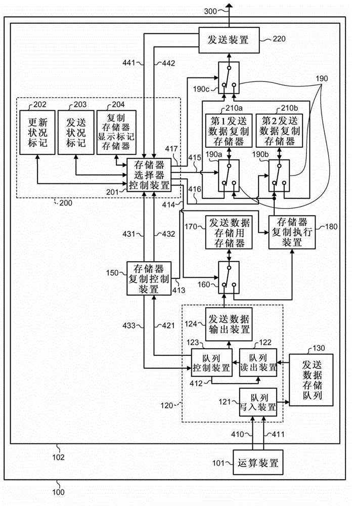
[0069] figure 1 It is a functional block diagram of PLC in Embodiment 1. figure 1 The illustrated PLC 100 has: an arithmetic unit 101 such as an MPU that generates transmission data 410; and a transmission control unit 102 that aggregates one or a plurality of transmission data 410 generated by the arithmetic unit 101 and outputs them to the transmission path 300 as indivisible data. . The transmission data 410 output from the transmission control device 102 is received by another PLC or equipment not shown via a transmission line 300 such as a bus.

[0070] The PLC 100 stores a system program and a control program in a memory not sho...

Embodiment approach 2

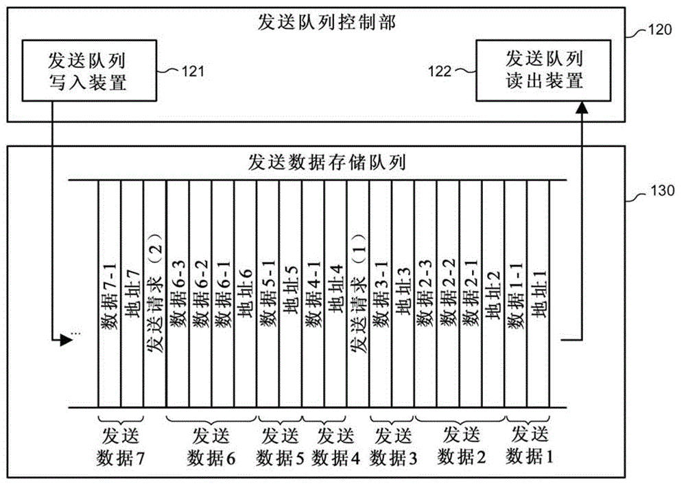
[0121] In Embodiment 1, if the Figure 5 In S101, the computing device 101 writes the sending data 410 into the transmission control device, then the sending data 410 is temporarily written into the sending data storage queue 130 in S102, is written into the sending data storage memory 170 in S104, and is written in the sending data storage memory 170 in S108. is copied to the transmission data copy memory 210. However, when the computing device 101 reads the transmission data 410 from the transmission control device later, and sets the read destination to the transmission storage queue 130, the transmission data 410 may have already been read from the transmission storage queue 130, so Failed to read send data 410. In addition, when the read target is set to the transmission data storage memory 170 or the transmission data copy memory 210, since the transmission data 410 is being transmitted while the queue reading device 122 is prohibited from reading from the transmission ...


PUM


Abstract

Provided is a transmission control device provided with data store memory into which data is written; a plurality of data copy memories into which the data that have been written into the data store memory are copied; a non-readout copy memory selection means for selecting one of the data copy memories from which the data has not been read out from among the plurality of the data copy memories; a memory copy means for copying the data that has been written into the data store memory into the data copy memory that has been selected by the non-readout copy memory selection means; a readout copy memory selection means for selecting the data copy memory into which the memory copy means has copied the data from among the plurality of data copy memories; and a data output means for reading out the data from the data copy memory that has been selected by the readout copy memory selection means and outputting thereof to the transmission means.

Description

technical field [0001] The present invention relates to a transmission control device for outputting transmission data written from an arithmetic unit in a programmable logic controller (hereinafter abbreviated as PLC) to a transmission path as inseparable data, a memory control device, and a device having the above transmission control device. PLC. Background technique [0002] In the PLC, the control program stored inside is executed by the computing device, the transmission data is generated, and the transmission data is sent as inseparable data to other PLCs, etc. via the transmission path. Here, the so-called indivisible data refers to a series of data composed of a plurality of pieces of information, and data whose original meaning cannot be interpreted if separated. Therefore, indivisible data must be sent in an undivided manner. [0003] Here, the time required to execute one cycle of the control program and the timing of generating transmission data during the exe...

Claims


Application Information

Patent Timeline
Patent Type & Authority Applications(China)
IPC IPC(8): G06F13/38
CPCG05B2219/15067G06F13/385G06F2213/3808G06F13/00G06F13/1657G06F13/1673G06F13/14G06F13/38G06F3/06G06F3/0601G06F3/061G06F3/0628G06F3/065G06F3/0683G06F3/0689G06F9/466G06F9/467G06F11/1451G06F11/1666
Inventor 日置荣太郎
Owner MITSUBISHI ELECTRIC CORP
Why Eureka
Try Eureka