
Base plate structure for baking oven with upper heat source

A technology of placing a heat source on top of an oven, applied in the field of ovens, can solve the problems of excessive food grilling, cumbersome operation, and difficulty in accurate control, and achieve the effects of avoiding heat loss, low heat loss rate, and small supporting area.

Active Publication Date: 2012-10-31
李琎熙
View PDF9 Cites 10 Cited by
  • Summary
  • Abstract
  • Description
  • Claims
  • Application Information

AI Technical Summary

Problems solved by technology

This structural solution has the following defects: In order to improve the heat transfer efficiency, the heat source should be installed as close as possible to the bottom surface of the baking pan, and the heat source is located in the base, and the base also absorbs heat during heating. , the residual heat on the base will continue to dissipate and act on the food, causing overheating and affecting the taste; if charcoal is used as the heat source, the method of adding or withdrawing charcoal is used to adjust the heating intensity, and the griller needs to constantly add or withdraw charcoal according to the eating speed , to avoid scorching food, and the operation is cumbersome and difficult to control accurately; in addition, the heat source is located under the baking pan, and the heat emitted by the heat source will pass through the baking pan and act on the bottom surface of the food, making it difficult for the operator to judge whether the food is raw or cooked from the upper surface It is easy to over-grill the food due to untimely observation, which will affect the taste
In view of the above-mentioned defects, the inventor has designed an oven with an upper heat source, but there is no suitable chassis (base and baking pan) with both strength and heat resistance. If the chassis of the lower-mounted oven is used, There are defects such as structural mismatch, high cost, inconvenient movement of the baking pan, and inability to leave the heat source in time

Method used


Image

  • Base plate structure for baking oven with upper heat source
  • Base plate structure for baking oven with upper heat source
  • Base plate structure for baking oven with upper heat source

Examples


Embodiment Construction

[0022] The present invention will be further described below with reference to the accompanying drawings.

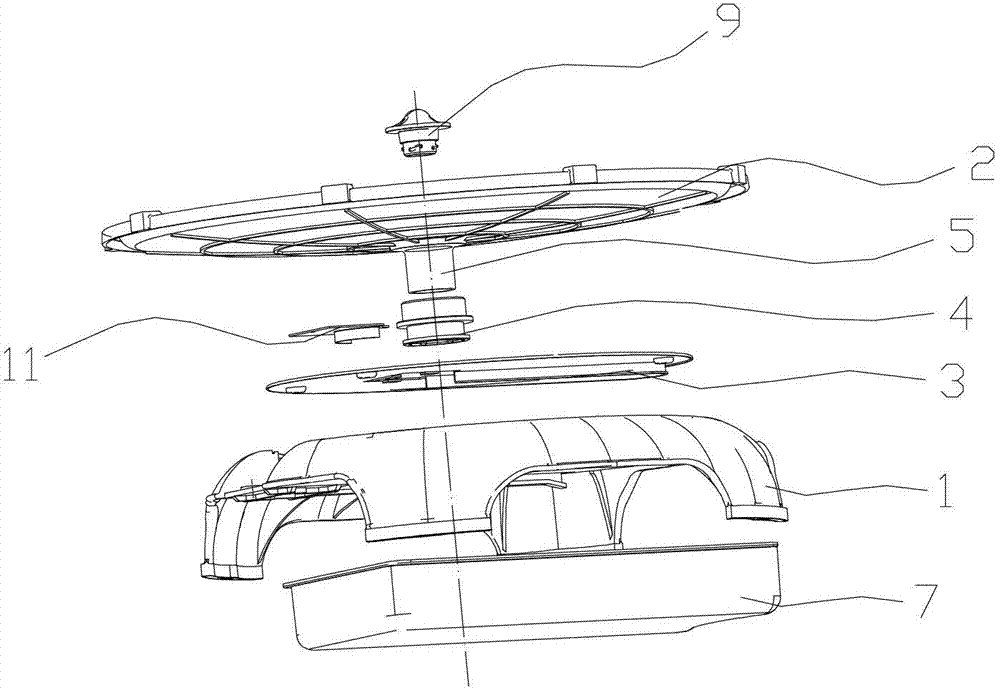
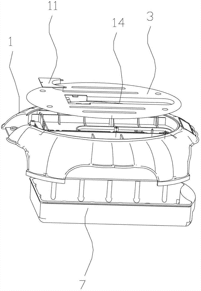
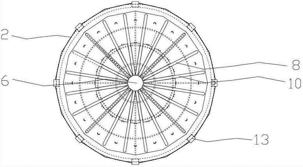
[0023] Such as Figure 1-Figure 6 As shown, the chassis structure of a heat source top-mounted oven described in this embodiment includes a base 1 and a baking pan 2. The base 1 is made of plastic material and a metal plate 3 is arranged in the middle. The metal plate 3 A long hole 14 is opened on the metal plate 3 and a metal support 4 that can slide in the long hole 14 is provided on the metal plate 3 , and the baking pan 2 is supported on the metal support 4 . The metal plate 3 is provided with a plurality of parallel reinforcing ribs to improve the strength.

[0024] A positioning protrusion 5 is provided in the middle of the bottom surface of the baking pan 2 , and the positioning protrusion 5 is embedded in a hollow metal support 4 , and the metal support 4 is higher than the metal plate 3 . The hollow part of the metal support 4 passes through the base 1, and th...


PUM


Abstract

The invention discloses a base plate structure for a baking oven with an upper heat source. The technical problem of absence of a base plate structure for the baking oven with the upper heat source at present is solved. The base plate structure comprises a base and a baking tray. The base is made of a plastic material, and a metal plate is arranged in the center of the base. A slotted hole is reserved in the metal plate, and a metal support part capable of sliding in the slotted hole is arranged on the metal plate. The baking tray is supported on the metal support part. The edge of the base plate structure is made of the plastic material with a poor heat transfer effect, and a metal part is arranged at a support part of the baking tray, so that the base plate structure is high in heat resistance, a user can be prevented from touching a base and being scalded, and heat loss is avoided at the same time; oil guiding channels are formed in the baking tray to guide waste oil out of the baking tray, so that the waste oil can be prevented from being deposited; the baking tray has a small support area and a low heat loss ratio; and the baking tray can reliably slide and rotate, so that the requirement that a user moves the baking tray out of or into a baking area or rotates the baking tray to select foods or baking temperature in a barbecue is met.

Description

technical field [0001] The invention relates to the technical field of ovens, in particular to a chassis structure of an oven with an upper heat source. Background technique [0002] The existing heat source bottom oven usually includes a base and a baking pan placed on the base, and the heat source is arranged between the baking pan and the base. The food placed on the baking tray is cooked by using the heat emitted upwards from the heat source placed below. This structural solution has the following defects: In order to improve the heat transfer efficiency, the heat source should be installed as close as possible to the bottom surface of the baking pan, and the heat source is located in the base, and the base also absorbs heat during heating. , the residual heat on the base will continue to dissipate and act on the food, causing overheating and affecting the taste; if charcoal is used as the heat source, the method of adding or withdrawing charcoal is used to adjust the h...

Claims


Application Information

Patent Timeline
Patent Type & Authority Applications(China)
IPC IPC(8): A47J37/06
CPCA47J37/06A47J37/07
Inventor 李琎熙
Owner 李琎熙
Learn More