Saw blade type numerical control cutting and chamfering machine

A technology of chamfering machine and saw blade, which is used in metal sawing equipment, sawing machine equipment, metal processing equipment and other directions, can solve the problems of poor effect, prone to eccentricity, and easily damaged blades.

Active Publication Date: 2012-10-31
ZHEJIANG AOTAI MACHINE MFG
View PDF6 Cites 14 Cited by
  • Summary
  • Abstract
  • Description
  • Claims
  • Application Information

AI Technical Summary

Problems solved by technology

[0002] A common saw blade type CNC cutting and chamfering machine includes a pipe clamping disc and a rotating disc, a rotating device is arranged between the clamping disc and the rotating disc, a cutting knife or a chamfering knife is arranged on the rotating disc, and the rotating disc rotates Drive the cutting knife or chamfering knife to cut or chamfer the pipe fittings, but the main problems of the existing saw blade type CNC cutting and chamfering machines are: 1. The cutting or chamfering cannot be completed at one time, and the rotating disk needs to be rotated for many times. Complete; 2. The pipe fittings are prone to eccentricity when clamping, so the cutting or chamfering effect is not good, and the blade is easy to be damaged; 3. The fixing of the blade is complicated, and it is not easy to fix and adjust

Method used


Image

  • Saw blade type numerical control cutting and chamfering machine
  • Saw blade type numerical control cutting and chamfering machine
  • Saw blade type numerical control cutting and chamfering machine

Examples


Embodiment Construction

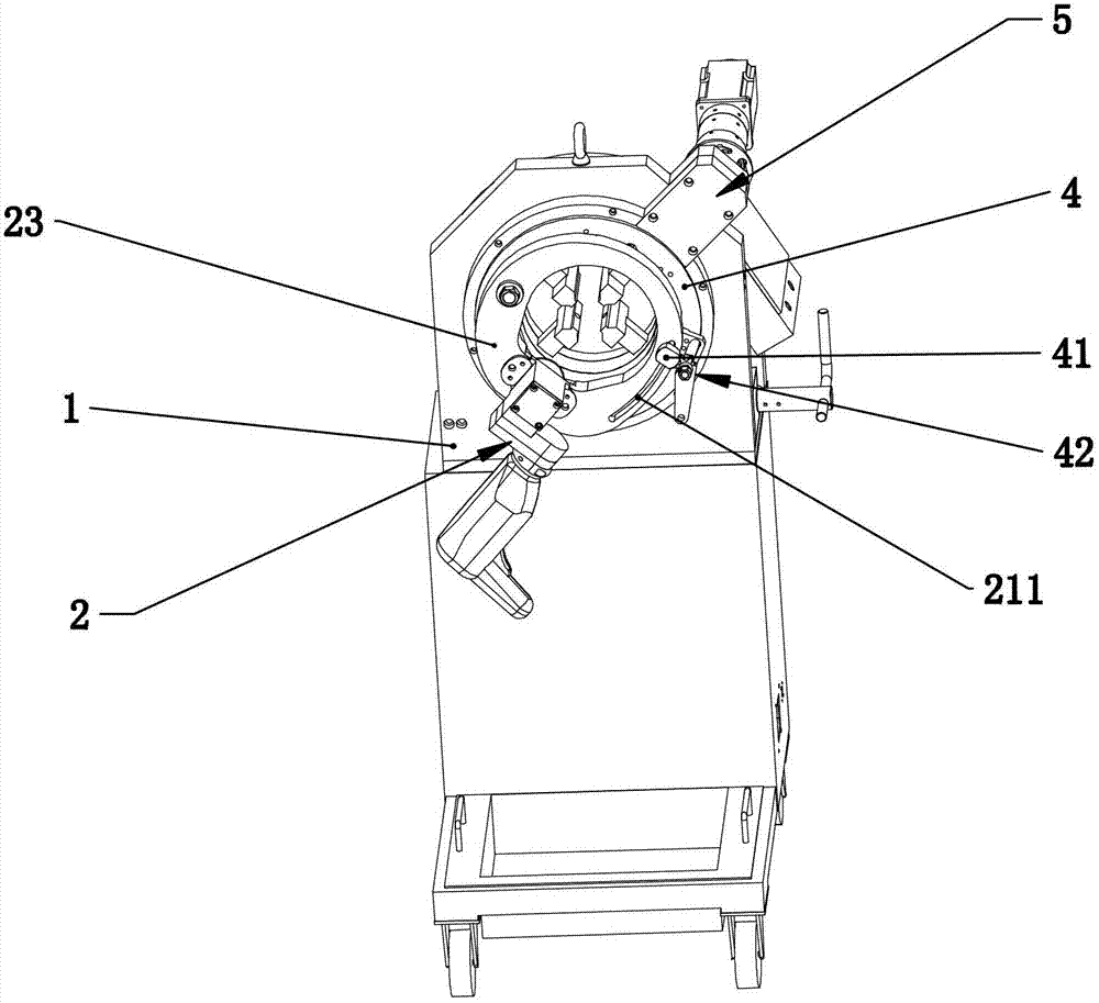
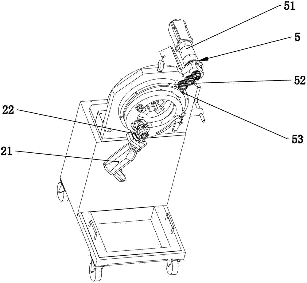
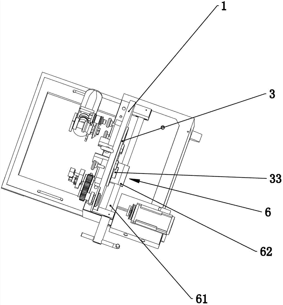
[0014] Such as figure 1 — Figure 5 As shown, a saw blade type CNC cutting and chamfering machine includes a frame 1, a cutting and chamfering device 2, a pipe clamping disk 3 and a rotating disk 4, and a rotating device 5 is arranged between the frame 1 and the rotating disk 4 , the rotating device 5 includes a motor 51, an output gear 52 and a gear plate 53, wherein the gear plate 53 is fixedly arranged on the rotary plate 4 or integrally arranged with the rotary plate 4, the output shaft of the motor 51 is linked with the output gear 52, and the output gear 52 meshes with the gear plate 53. In the example of the present invention, the clamping plate 3 and the frame 1 form a rotational fit, and the rotating plate 4 is hingedly provided with a cutting and chamfering device 2 mounting bracket 23, which One side of 23 is hinged with the rotating disk 4, and the other side is provided with a long through hole 211. The rotating disk 4 is fixedly provided with a limit pin 41, and...


PUM


Abstract

The invention relates to a cutting and chamfering machine, in particular to a saw blade type numerical control cutting and chamfering machine for performing chopping cutting or chamfering on a hollow pipe fitting. The adopted technical scheme is that the saw blade type numerical control cutting and chamfering machine is characterized in that a clamping disc and a rack are in running fit, wherein a rotary disc is hinged with a cutting and chamfering device mounting rack; one side of the mounting rack is hinged with the rotary disc, and the other side of the mounting rack is provided with a long through hole; the rotary disc is provided with a mounting rack locking mechanism at a position of a limiting pin; the cutting and chamfering machine comprises a motor, a transmission component and a cutting or chamfering blade mounting rack; the motor is fixedly arranged on the mounting rack; the transmission component is fixedly arranged on the mounting rack through a bearing; and a motor output shaft is in linked and matched with the transmission component. By using the technical scheme, cutting or chamfering treatment can be performed on the pipe fitting; and in addition, the mechanism can realize one-time cutting or chamfering of the pipe fitting, and the cutting and chamfering machine automatically withdraws to the original position with great convenience.

Description

technical field [0001] The invention relates to a cutting and chamfering machine, in particular to a cutting and chamfering machine for cutting or chamfering hollow pipes. Background technique [0002] A common saw blade type CNC cutting and chamfering machine includes a pipe clamping disc and a rotating disc, a rotating device is arranged between the clamping disc and the rotating disc, a cutting knife or a chamfering knife is arranged on the rotating disc, and the rotating disc rotates Drive the cutting knife or chamfering knife to cut or chamfer the pipe fittings, but the main problems of the existing saw blade type CNC cutting and chamfering machines are: 1. The cutting or chamfering cannot be completed at one time, and the rotating disk needs to be rotated for many times. Complete; 2. The pipe fittings are prone to eccentricity when clamping, so the cutting or chamfering effect is not good, and the blade is easy to be damaged; 3. The fixing of the blade is complicated, ...

Claims


Application Information

Patent Timeline
IPC IPC(8): B23D57/00
Inventor 项深泽项光春项玉振胡耀
Owner ZHEJIANG AOTAI MACHINE MFG
Why Eureka
Try Eureka