Air floatation circumferential chamfering machine

A chamfering machine and air flotation technology, applied in metal processing machinery parts, large fixed members, metal processing equipment, etc., can solve problems such as low work efficiency, inconvenient operation, and worker injuries.

Inactive Publication Date: 2016-08-10
CHUNG CHUN STEEL MOLD MACHINERY IND SUZHOU
View PDF10 Cites 1 Cited by
  • Summary
  • Abstract
  • Description
  • Claims
  • Application Information

AI Technical Summary

Problems solved by technology

[0002] Grinding, chamfering, polishing and other operations around the workpiece are often completed on the working platform, and the workpiece is fixed on the working platform. Due to the limited working range of the processing tool, it is often necessary to rotate the workpiece when processing different parts. The chamfering machine is used as the For example, when...

Method used


Image

  • Air floatation circumferential chamfering machine
  • Air floatation circumferential chamfering machine

Examples


Embodiment Construction

[0017] The present invention will be further described below in conjunction with the accompanying drawings. The following examples are only used to illustrate the technical solution of the present invention more clearly, but not to limit the protection scope of the present invention.

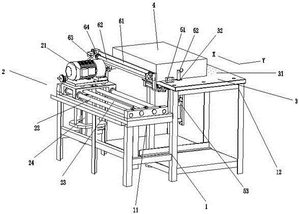
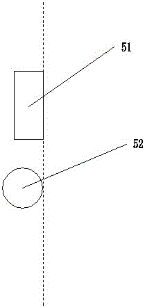
[0018] Such as Figure 1-2 Shown, a kind of air-floating four-sided chamfering machine comprises frame 1, feeding device 2 and discharging device, and feeding device 2 and discharging device are arranged on frame 1, and feeding device 2 comprises cutter head, Motor 21, motor guide plate, lifting cylinder 24, cylinder guide sleeve, rodless cylinder rod 23 and guide shaft 22, the top of the feeding device has a horizontal workpiece placement platform 3, specifically, the frame 1 becomes a ladder type, and the feed device Be positioned at lower lower frame 11, discharge device is positioned at higher upper frame 12, under the drive of motor 21 and lift cylinder 24, cutter head can be chamfered alo...


PUM


Abstract

The invention discloses an air floatation circumferential chamfering machine. The air floatation circumferential chamfering machine comprises a rack, a feed gear and a discharging device, wherein the feed gear and the discharging device are arranged on the rack, the feed gear comprises a cutter bit, a motor, a motor guide plate, a lifting cylinder, a cylinder guide sleeve, a rodless cylinder rod and a guide shaft, a horizontal workpiece placing table is arranged at the upper part of the discharging device, a plurality of ventilation holes are evenly formed in the horizontal workpiece placing table, the discharging device is further provided with an air supply mechanism, and the air supply mechanism supplies air from bottom to top through the ventilation holes. When the chamfering machine chamfers the circumference of a workpiece, the workpiece can be more easily rotated.

Description

technical field [0001] The invention relates to a chamfering machine, in particular to an air-floating four-sided chamfering machine, which belongs to the technical field of mechanical processing equipment. Background technique [0002] Grinding, chamfering, polishing and other operations around the workpiece are often completed on the working platform, and the workpiece is fixed on the working platform. Due to the limited working range of the processing tool, it is often necessary to rotate the workpiece when processing different parts. The chamfering machine is used as the For example, when the existing chamfering machine is chamfering, it is often convenient to chamfer only one side of the workpiece. When chamfering is required on all sides, the workpiece must be manually rotated. For large workpieces, frequent rotation of the workpiece is not only inconvenient to operate , the work efficiency is low, and the workers will be injured by turning the workpiece. Contents of...

Claims


Application Information

Patent Timeline
IPC IPC(8): B23D79/00B23Q1/26
CPCB23D79/00B23Q1/26
Inventor 黄勇
Owner CHUNG CHUN STEEL MOLD MACHINERY IND SUZHOU
Why Eureka
Try Eureka