Manufacturing method of motor rotor

A manufacturing method and technology for motor rotors, which are applied in the manufacture of motor generators, stator/rotor bodies, electrical components, etc., can solve the problems of failing to fill the entire mold smoothly, increasing time, and slow flow of molten copper water.

Inactive Publication Date: 2012-10-31
张金锋
View PDF3 Cites 3 Cited by
  • Summary
  • Abstract
  • Description
  • Claims
  • Application Information

AI Technical Summary

Problems solved by technology

[0003] Although the existing manufacturing method can form a copper ring on the outside of the laminated silicon steel sheet, when the molten copper water is poured into the mold in the existing motor rotor manufacturing method, it mainly depends on the flow of the molten copper water in the mold to fill the ring. The entire mold is used to form the copper ring outside the laminated silicon steel sheet. However, the molte

Method used


Image

  • Manufacturing method of motor rotor
  • Manufacturing method of motor rotor
  • Manufacturing method of motor rotor

Examples


Embodiment Construction

[0030] In order to understand the technical features and practical effects of the present invention in detail, and to implement them according to the contents of the description, the preferred embodiment shown in the accompanying drawings will be described in detail as follows:

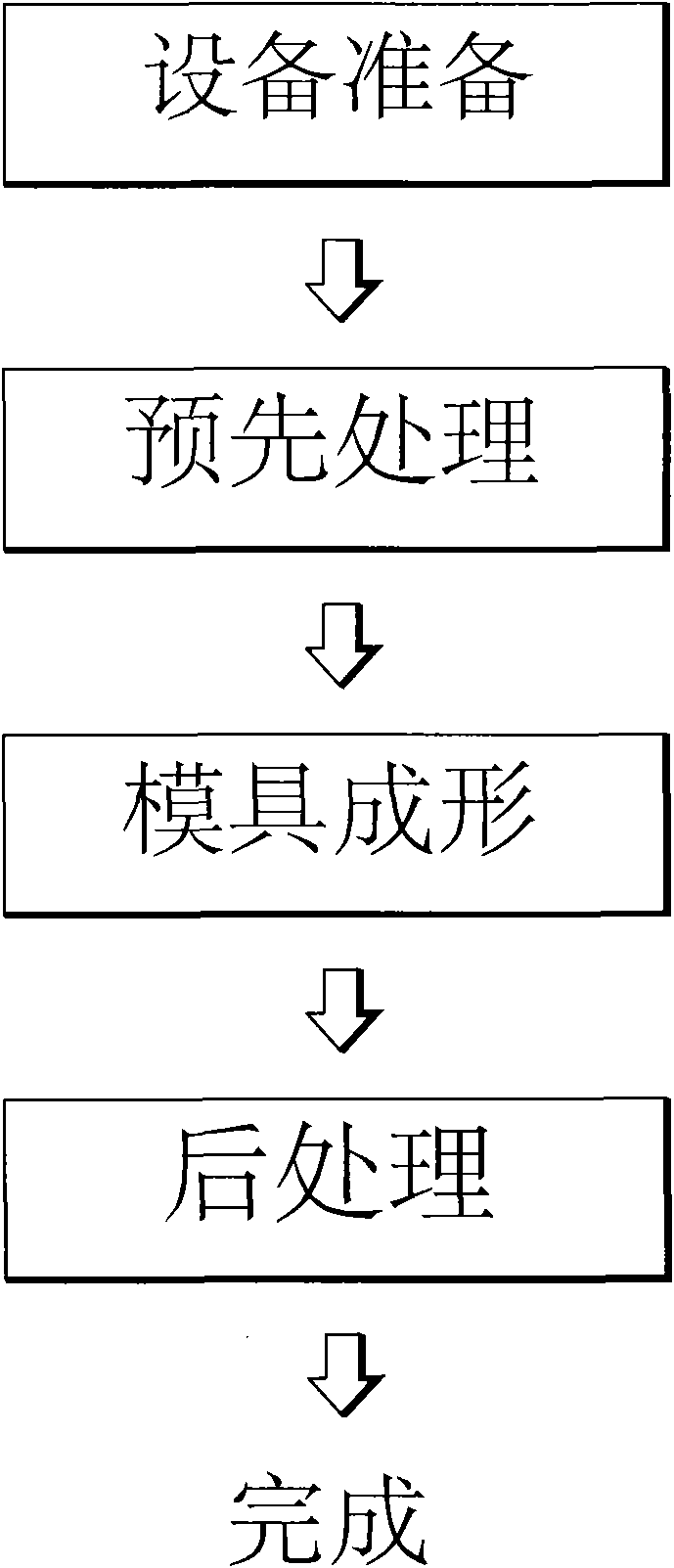
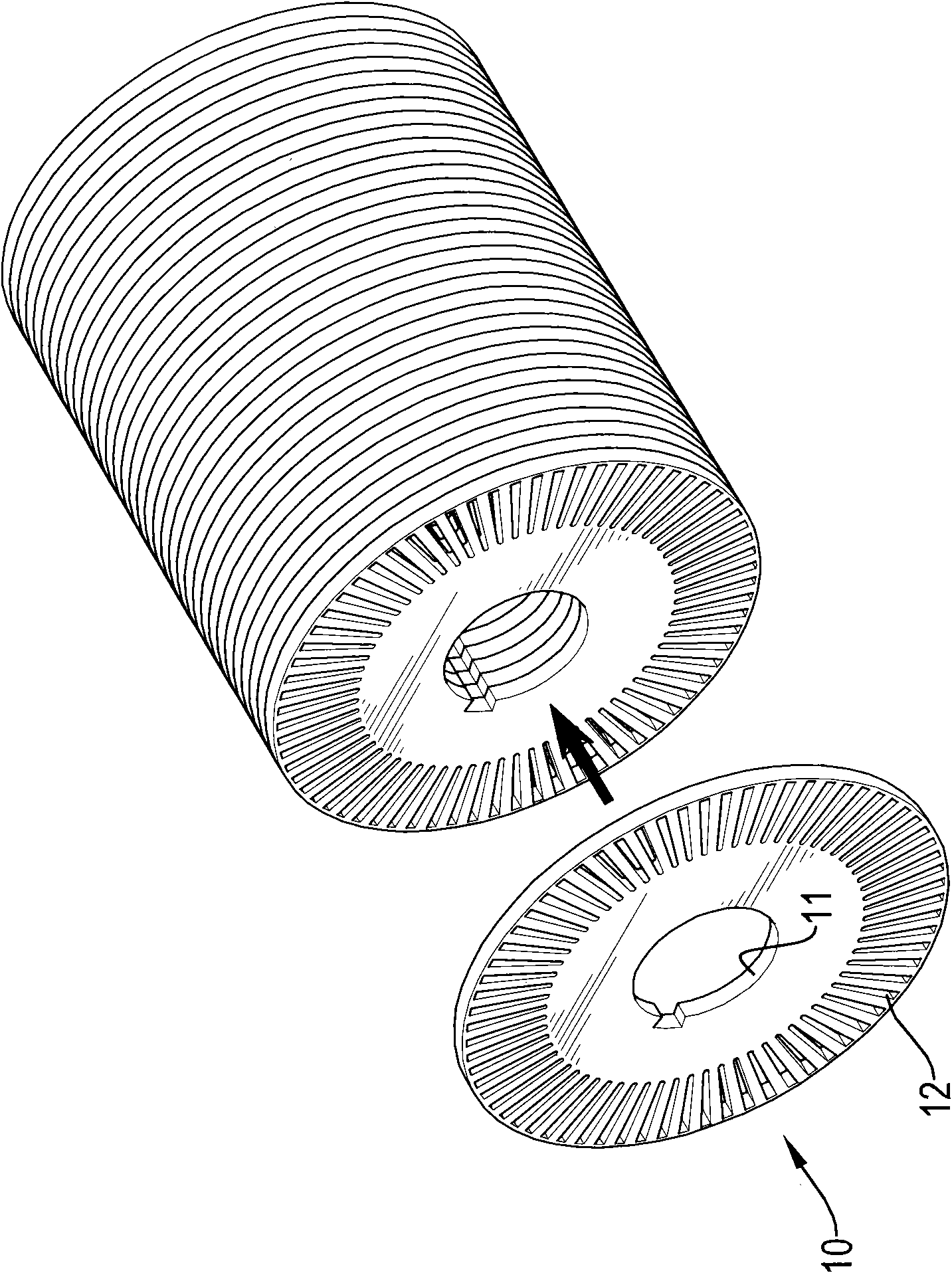
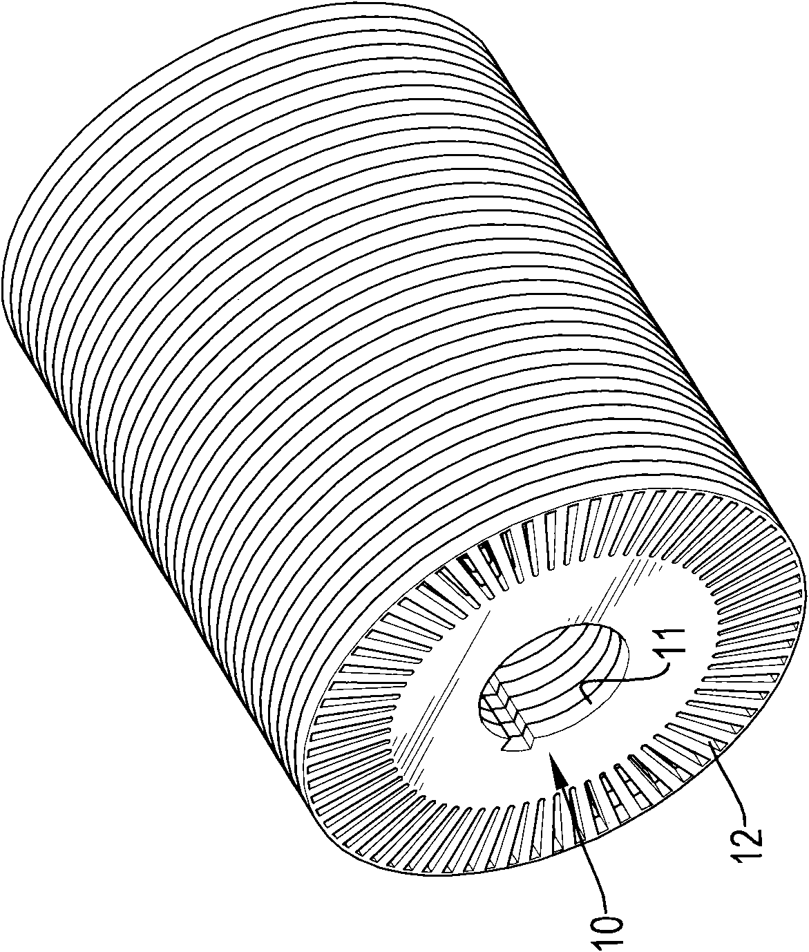
[0031] The present invention is a method for manufacturing a motor rotor, please refer to Figure 1 to Figure 10 As shown, the motor rotor manufacturing method includes:

[0032] (A), material preparation: prepare a plurality of silicon steel sheets 10, a shaft 20, a mold 30 and a surface treatment device, wherein each silicon steel sheet 10 is provided with a shaft hole 11 through the center, and is spaced near the outer periphery A plurality of copper holes 12 are penetrated through, and a combination hole 21 is recessed on the outer surface of both ends of the shaft rod 20, and two positioning plates 23 are respectively fixed to the two ends of the shaft rod 20 by a locking piece 22, the mold The ...


PUM


Abstract

A manufacturing method of a motor rotor comprises the steps of preparing a plurality of silicon-steel plates, a shaft lever, and a mould provided with both an injection opening and a suction opening, sleeving the shaft lever into the laminated silicon-steel plates, placing the shaft lever and the silicon-steel plates into the mould, conducting suction by the suction opening to allow the interior of the mould to be in a vacuum state, injecting molten copper into the mould via the injection opening, allowing the molten copper to flow to the suction opening under the effect of the vacuum state, so as to be filled in the whole mould, cooling the mould, allowing the molten copper to form a copper ring on the silicon-steel plates, and cooling to the room temperature, thereby accomplishing the manufacturing of the motor rotor. The manufacturing method of the motor rotor can increase the product yield.

Description

technical field [0001] The invention relates to a method for manufacturing a motor rotor, in particular to a method for manufacturing a motor rotor that can improve product yield. Background technique [0002] When the existing motor rotor is manufactured, a plurality of silicon steel sheets are first laminated and then positioned through a shaft, and the shaft and the silicon steel sheets are heated and put into a mold, and a molten copper water is poured into the In the mold, a copper ring is formed on the outside of each silicon steel sheet, and after cooling, the mold is opened to take out the silicon steel sheet with the copper ring and the shaft rod, which completes the manufacture of the existing motor rotor; [0003] Although the existing manufacturing method can form a copper ring on the outside of the laminated silicon steel sheet, when the molten copper water is poured into the mold in the existing motor rotor manufacturing method, it mainly depends on the flow of...

Claims


Application Information

Patent Timeline
IPC IPC(8): H02K15/02H02K15/12
Inventor 张金锋
Owner 张金锋
Why Eureka
Try Eureka