Supercharge Your Innovation With Domain-Expert AI Agents!

Step-down type power factor correction (PFC) circuit

A circuit and rectifier circuit technology, applied in electrical components, regulating electrical variables, high-efficiency power electronic conversion, etc., can solve the problem of small duty cycle of step-down PFC circuits, and achieve the requirements of improving switching efficiency, reducing parameters, reducing The effect of production costs

Active Publication Date: 2014-11-26
MORNSUN GUANGZHOU SCI & TECH
View PDF4 Cites 0 Cited by
  • Summary
  • Abstract
  • Description
  • Claims
  • Application Information

AI Technical Summary

Problems solved by technology

[0022] In view of this, the present invention will solve the problem that the duty cycle of the step-down PFC circuit is too small, the present invention provides a step-down PFC circuit, its maximum duty cycle is not affected by the formula (2), formula in the background technology (3) limited, can reach above 0.6, even above 0.75

Method used


Image

  • Step-down type power factor correction (PFC) circuit
  • Step-down type power factor correction (PFC) circuit
  • Step-down type power factor correction (PFC) circuit

Examples


no. 1 example

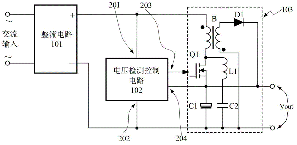
[0060] image 3 A schematic diagram of the first embodiment is shown, and its connection relationship and working principle have been introduced in detail in the section of the summary of the invention, so details are not repeated here. Here we will mainly describe the specific experimental parameters and measured results in detail. image 3 The circuit is designed as a step-down PFC circuit with an input operating voltage range of 85VAC to 264VAC, an output of 75W, and an output voltage of 20V.

[0061] The rectifier circuit is composed of four 1N4007, the common IRF740B is used for N-MOS tube Q1, the capacitor C1 is a 3300uF / 25V electrolytic capacitor, the diode D1 is directly connected in parallel with common cathode MBRF20H150, the capacitor C2 is 6800pF / 630V, and the transformer B is directly selected The standard product KA5038-BL, the inductance L1 is a rod-shaped inductance of 6.8uH / 2A. Among them, the voltage detection control circuit is directly built by the ATMEGA3...

no. 2 example

[0075] Figure 9 shows the second embodiment, where the first embodiment image 3 On the basis of , a second winding Ns2 is added to the secondary side of the transformer B, and a second diode D2, a third diode D3, and a second inductor L2 are added to the circuit at the same time, thus obtaining Figure 9 The same-named end of the secondary winding Ns2 of the transformer B is connected to the anode of the diode D2, the cathode of the diode D2 is connected to one end of the inductor L2, and the other end of the inductor L2 is connected to the positive output end of the output voltage Vout; the cathode of the diode D2 is connected to the cathode of the diode D3 at the same time, and the diode D3 The anode of the transformer B is connected to the opposite terminal of the secondary winding Ns2 of the transformer B, and is connected to the negative output terminal of the output voltage Vout at the same time.

[0076] This is a typical forward output circuit. When the N-MOS transi...


PUM


Abstract

The invention discloses a step-down type power factor correction (PFC) circuit. A source electrode of an N-channel metal oxide semiconductor (N-MOS) tube in a flyback circuit is connected to a positive output of an output end, and a series loop of a first inductor and a second capacitor is used as a demagnetization loop, so that when the N-MOS tube in the flyback circuit is conducted to magnetize a transformer, magnetizing current can directly supply electricity to a load; and when the N-MOS tube in the flyback circuit is turned off, a flyback output circuit supplies electricity to the load. By the step-down type PFC circuit, the working duty ratio D of the N-MOS tube is improved, and the problem of too small duty ratio of the step-down PFC circuit when the output voltage is lower than 48V is solved; and the energy in the second capacitor directly discharges to the load through the first inductor when the N-MOS tube is conducted next time, so that the working efficiency of the circuit is improved.

Description

technical field [0001] The invention relates to an AC-DC circuit, in particular to an AC-DC converter for step-down power factor correction. Background technique [0002] There are many AC to DC circuits, and industrial and civil power supply generally use AC power supply. Taking civilian use as an example, my country uses 220VAC / 50Hz, America uses 120VAC or 110VAC, and the frequency is 60Hz, while the United Kingdom uses 240VAC / 50Hz, and other countries and regions It is also different. Generally speaking, there are two frequencies: 50Hz or 60Hz, and the working voltage is about 110V and 220V. Its characteristic is that the direction of the amplitude of the voltage (or current) changes periodically with time, such as figure 1 shown. [0003] figure 1 The alternating current that changes sinusoidally over time is called alternating sinusoidal voltage, and the time required for one change is called the cycle of alternating voltage, which is represented by T. The 220V referre...

Claims


Application Information

Patent Timeline
Patent Type & Authority Patents(China)
IPC IPC(8): H02M7/217H02M3/335H02M1/42
CPCY02B70/126Y02B70/10
Inventor 尹向阳王保均
Owner MORNSUN GUANGZHOU SCI & TECH
Features
  • R&D
  • Intellectual Property
  • Life Sciences
  • Materials
  • Tech Scout
  • Unparalleled Data Quality
  • Higher Quality Content
  • 60% Fewer Hallucinations
Learn More