Heat-insulating panel for use in buildings

A heat insulation board and building technology, applied in the direction of building structure, building, building components, etc., can solve the problems of cost increase, time-consuming, low cost and high efficiency, etc., and achieve sufficient heat storage and high heat insulation effect Effect

Inactive Publication Date: 2012-10-31
HITACHI LTD
View PDF3 Cites 3 Cited by
  • Summary
  • Abstract
  • Description
  • Claims
  • Application Information

AI Technical Summary

Problems solved by technology

[0022] In short, in a building insulation panel (insulation panel) for the purpose of connecting a single structure formed by combining a conventional vacuum insulation material and a heat storage material (or heat insulation material) in a planar shape, in order to In order to realize a vacuum insulation material that can reduce thermal bridges, the current situation is that the cost increases or the development of materials takes time. Therefore, as a result, the suppression measures for thermal bridges have not achieved low cost and high efficiency, and there is a problem of lack of versatility.

Method used


Image

  • Heat-insulating panel for use in buildings
  • Heat-insulating panel for use in buildings
  • Heat-insulating panel for use in buildings

Examples


Embodiment 1

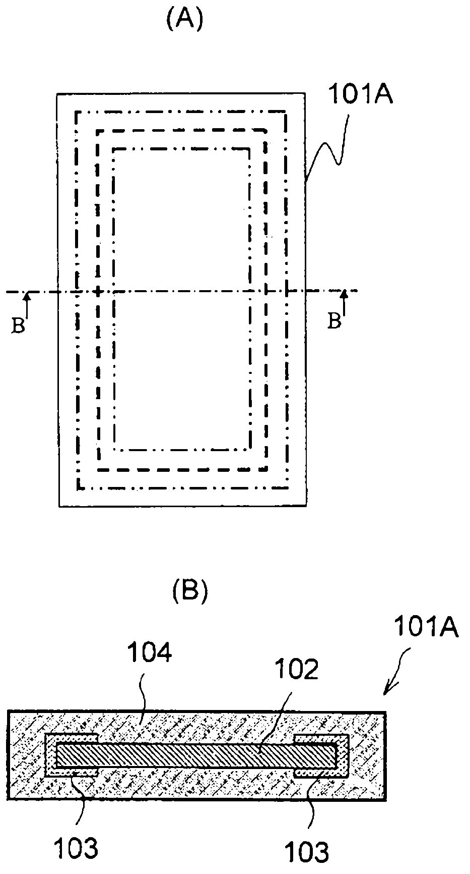
[0047] figure 1 It is a diagram showing a schematic configuration of a heat insulating panel 101A for a building according to Example 1 of the present invention, the diagram (A) is a plan view showing the interior partly seen through from above, and the diagram (B) is B-B of the diagram (A) A side sectional view in the width direction viewed along the line.

[0048] refer to figure 1 (A) and (B), the heat insulating panel 101A for a building has a basic structure in which the entire flat vacuum heat insulating material 102 is covered with the heat insulating material 104 , and the entire periphery of the vacuum heat insulating material 102 is covered with The method is equipped with a latent heat storage material 103 formed in a substantially frame-like shape connected from one main surface of the vacuum heat insulating material 102 to the other main surface over a side wall. The latent heat storage material 103 is provided for relieving thermal bridges caused by heat leakag...

Embodiment 2

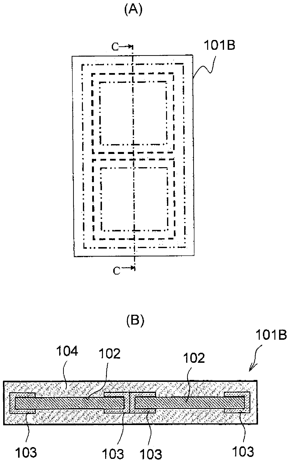
[0059] figure 2 It is a diagram showing a schematic configuration of a heat insulating panel 101B for a building according to Example 2 of the present invention, the diagram (A) is a top view showing the interior partly seen through from above, and the diagram (B) is C-C of the diagram (A) A side sectional view along the length of the line.

[0060] refer to figure 2 (A) and (B), the heat insulating panel 101B for a building is basically formed by covering the whole of a plurality (here, two) of flat vacuum heat insulating materials 102 arranged at predetermined intervals with a heat insulating material 104 . In addition to the structure, a plurality of (here, two) latent heat storage materials 103 are provided so as to cover the vicinity of the entire periphery of each vacuum heat insulating material 102, and the latent heat storage materials 103 form one main surface of each vacuum heat insulating material 102. A substantially frame-like shape connected to the other side...

Embodiment 3

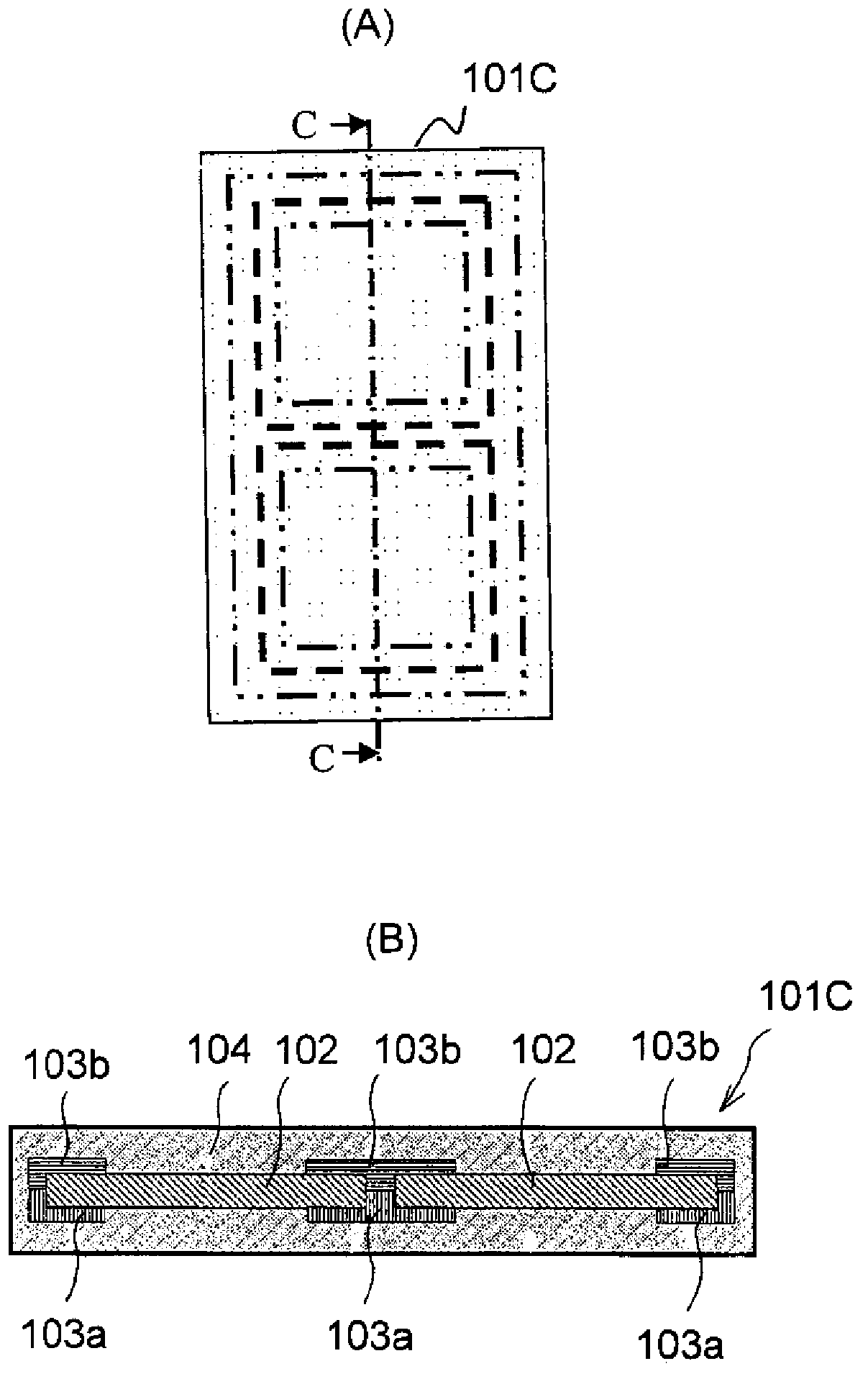
[0066] image 3 It is a diagram showing a schematic configuration of a heat insulating panel 101C for a building according to Example 3 of the present invention, the diagram (A) is a plan view showing the interior partly seen through from above, and the diagram (B) is C-C of the diagram (A) A side sectional view along the length of the line.

[0067] refer to image 3(A) and (B), the heat insulating panel 101C for a building is basically formed by covering the whole of a plurality (here, two) of flat vacuum heat insulating materials 102 arranged at predetermined intervals with the heat insulating material 104 . In addition to the structure, the first latent heat storage material 103a and the second latent heat storage material 103b are equipped, and the first latent heat storage material 103a, the first latent heat storage material 103a is formed from each of the vacuum heat insulating materials 102 to one The main surface side is connected in a substantially lattice frame s...


PUM

PropertyMeasurementUnit
Thicknessaaaaaaaaaa
Thicknessaaaaaaaaaa
Thicknessaaaaaaaaaa

Abstract

Provided is a heat-insulating panel for use in buildings that has strong heat-insulating effects and can store heat when individual heat-insulating panels, which combine a vacuum-insulation material and a heat-storing material, are connected in a planar manner. Said heat-insulation panel (101A) has a basic structure obtained by covering the entirety of a plate-shaped vacuum-insulation material (102) with a heat-insulation material (104), and is provided with a latent heat storage material (103) that is arranged in a substantially frame like shape extending from one main surface of the vacuum-insulation material (102), wrapping around the sidewall thereof, and connecting to the other main surface thereof, so as to cover the entire peripheral edge of the vacuum-insulation material (102). The latent heat storage material (103) is provided to mitigate heat bridging that results from heat leakage between high temperature and low temperature parts in the vacuum-insulation material (102) under usage conditions that undergo changes in temperature, by means of latent heat. The heat-insulation material (104) is arranged in a manner such that the heat-insulation material covers the entire surface of the latent heat storage material (103) and the entire exposed surface of the vacuum-insulation material (102).

Description

technical field [0001] The present invention relates to a thermal insulation panel for buildings, which is suitable for use in combination with an air-conditioning and hot water supply system, and is a single structure with excellent thermal insulation performance and a simple structure for alleviating the heat leakage of a vacuum thermal insulation material by the latent heat of a latent heat storage material. The above-mentioned air-conditioning and hot-water supply system includes refrigeration and air-conditioning circuits using new refrigerants with low global warming potential (GWP), and is designed for new-century houses with high ecological (environmental response) effects. Background technique [0002] In recent years, countermeasures for suppressing global warming have become urgent, and energy saving has been demanded even in residential environments. In order to realize these measures, it is desired to reduce energy consumption by improving the thermal insulation...

Claims


Application Information

Patent Timeline
IPC IPC(8): E04B1/80
CPCF28D20/02Y02B80/12E04B1/803Y02A30/242Y02B80/10Y02E60/14
Inventor 内田麻理小谷正直小松智弘嘉本大五郎
Owner HITACHI LTD
Why Eureka
Try Eureka