Ultralow-temperature liquefied gas pressure vessel and heat insulation method

A technology for liquefied gas and pressure vessels, applied in the field of pressure vessels, can solve the problems of affecting the adiabatic effect of ultra-low temperature liquefied gas pressure vessels, and cannot completely eliminate heat conduction, convection and radiation, etc. safety effect

Pending Publication Date: 2022-04-22
JIANGYIN FUREN HIGH TECH
View PDF11 Cites 0 Cited by
  • Summary
  • Abstract
  • Description
  • Claims
  • Application Information

AI Technical Summary

Problems solved by technology

[0004] One is that the support structure between the inner container and the outer container will produce a certain amount of heat transfer, which affects the insulation effect of the ultra-low temperature liquefied gas pressure vessel
[0005] Second, although the thermal insulation materials in the mezzanine space can enhance the thermal insulation effect, the use of thermal insulation materials is still a passive thermal insulation method after all, which cannot completely eliminate heat conduction, convection, and radiation, which will also affect ultra-low temperature liquefied gas. Insulation effect of pressure vessel

Method used


Image

  • Ultralow-temperature liquefied gas pressure vessel and heat insulation method

Examples


Embodiment Construction

[0031] The specific implementation manners of the present invention will be further described below in conjunction with the drawings and examples. The following examples are only used to illustrate the technical solution of the present invention more clearly, but not to limit the protection scope of the present invention.

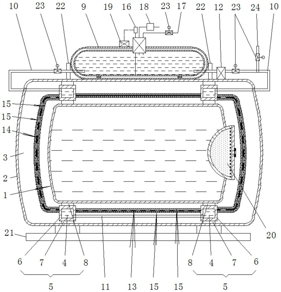
[0032] Such as figure 1Shown is an embodiment of an ultra-low temperature liquefied gas pressure vessel and the heat insulation method of the present invention, including an inner vessel 1, an outer vessel 2, a interlayer space 3 formed between the inner vessel 1 and the outer vessel 2, a support A support assembly between the inner container 1 and the outer container 2, the support assembly includes a pair of support rings 6 with an annular hollow cavity 4, arranged on the outer periphery of the support ring 6 and spaced along the circumferential direction A number of outer support heat insulation pads 7 arranged to support the inner wall of the outer con...


PUM


Abstract

The invention discloses an ultralow-temperature liquefied gas pressure container and a heat insulation method. The pressure container comprises an inner container, an outer container and a supporting assembly supported between the inner container and the outer container. The supporting assembly comprises a pair of supporting rings with annular hollow inner cavities and a plurality of inner supporting heat insulation pads arranged on the inner peripheries of the supporting rings at intervals in the circumferential direction and used for supporting the outer wall of the inner container. A liquid nitrogen tank is arranged on the upper portion of the outer container, a pair of liquid nitrogen circulating pipes are led out downwards from an inner liquid nitrogen area of the liquid nitrogen tank, and the pair of liquid nitrogen circulating pipes correspondingly communicate with annular hollow inner cavities of the pair of supporting rings after penetrating through the container wall of the inner container. The annular hollow inner cavities of the pair of supporting rings are filled with liquid nitrogen through a liquid nitrogen tank and a pair of liquid nitrogen circulating pipes, a liquid nitrogen communicating pipe is arranged between the annular hollow inner cavities of the pair of supporting rings, and a liquid nitrogen circulating pump is connected to one of the liquid nitrogen circulating pipes in series. The heat insulation effect of the ultralow-temperature liquefied gas pressure vessel is improved.

Description

technical field [0001] The invention relates to the technical field of pressure vessels, in particular to an ultra-low temperature liquefied gas pressure vessel and a heat insulation method. Background technique [0002] Ultra-low temperature liquefied gas storage pressure vessel is a cryogenic pressure vessel used to store ultra-low temperature liquefied gas. It adopts a double-layer structure, including an inner container and an outer container. A vacuum interlayer space is formed between the inner container and the outer container to isolate external heat. Transfer to ensure the safety of the cryogenic liquefied gas in the inner container. In order to improve the thermal insulation performance, thermal insulation materials are usually installed in the interlayer space to reduce heat conduction, convection and radiation, so as to achieve the purpose of thermal insulation and storage of cryogenic liquids. The vacuuming of the interlayer and the setting of thermal insulatio...

Claims


Application Information

Patent Timeline
IPC IPC(8): F17C3/02F17C3/04F17C13/00F17C13/02F17C13/04F17C13/08
CPCF17C3/02F17C3/04F17C13/021F17C13/04F17C13/00F17C13/08F17C2203/014F17C2203/0308F17C2203/0345F17C2203/0366F17C2205/0103F17C2205/0388F17C2250/0408
Inventor 徐兴宝朱明国计徐伟许惠钢罗展鹏徐谷钱丽君
Owner JIANGYIN FUREN HIGH TECH
Why Eureka
Try Eureka