Eureka AIR delivers breakthrough ideas for toughest innovation challenges, trusted by R&D personnel around the world.

Wind turbine rotor blade components and methods of making same

A technology for wind turbines and blades, applied in the field of structural pre-formed layers, which can solve problems such as misalignment and misalignment, does not support manufacturing or molding processes, and affects the overall manufacturing time and cost of turbine blades

Active Publication Date: 2012-10-31
SIEMENS GAMESA RENEWABLE ENERGY SERVICE GMBH
View PDF5 Cites 21 Cited by
  • Summary
  • Abstract
  • Description
  • Claims
  • Application Information

AI Technical Summary

Problems solved by technology

Since there is no inherent structural shape in the fiber fabric, these prior art materials are prone to fiber washout during resin infusion or infusion, which leads to undesirable fabric layer and composite wrinkling in the formed spar caps, Bending, Misalignment and Misdirection
[0013] Also, prior art fiber-reinforced fabric layers and composites are prone to shrinkage during curing of the bonding resin
Bonding resins may shrink considerably during resin curing, such that resin shrinkage may cause undesired creases, kinks and bows in fabric layers and composites during the fabrication of structural components
[0014] Furthermore, the form of the prior art material does not support a tightly controlled manufacturing or molding process, which in turn requires the use of additional materials
Therefore, manufacturing techniques and methods using fiber reinforced or cellulosic materials can affect the overall manufacturing time and cost of turbine blade production

Method used


Image

  • Wind turbine rotor blade components and methods of making same
  • Wind turbine rotor blade components and methods of making same
  • Wind turbine rotor blade components and methods of making same

Examples


Embodiment Construction

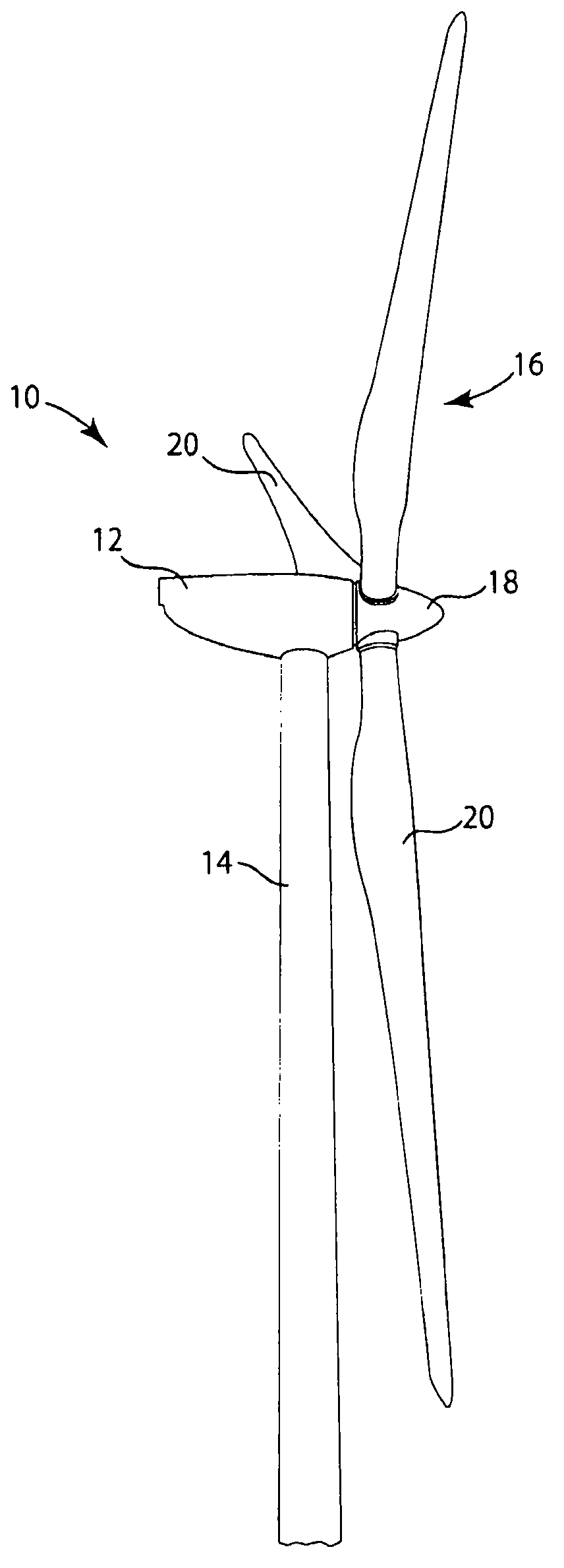
[0062] reference figure 1 with 2 In one aspect, the present invention provides a wind turbine 10 that includes a nacelle 12 mounted on a tower 14 and a rotor 16 that includes a rotating hub 18 and turbine blades 20. The rotor 16 is operatively connected with a generator (not shown) installed in the nacelle 12. The tower 14 exposes the blades 20 to the wind. The blades 16 capture wind energy and convert the wind energy into rotational motion, and the generator converts it into electrical energy. figure 1 The wind turbine 10 shown in FIG. 1 includes three turbine blades 20, but the invention is not particularly limited to three blades 20, and it is anticipated that the rotor 16 can include more or fewer turbine blades.

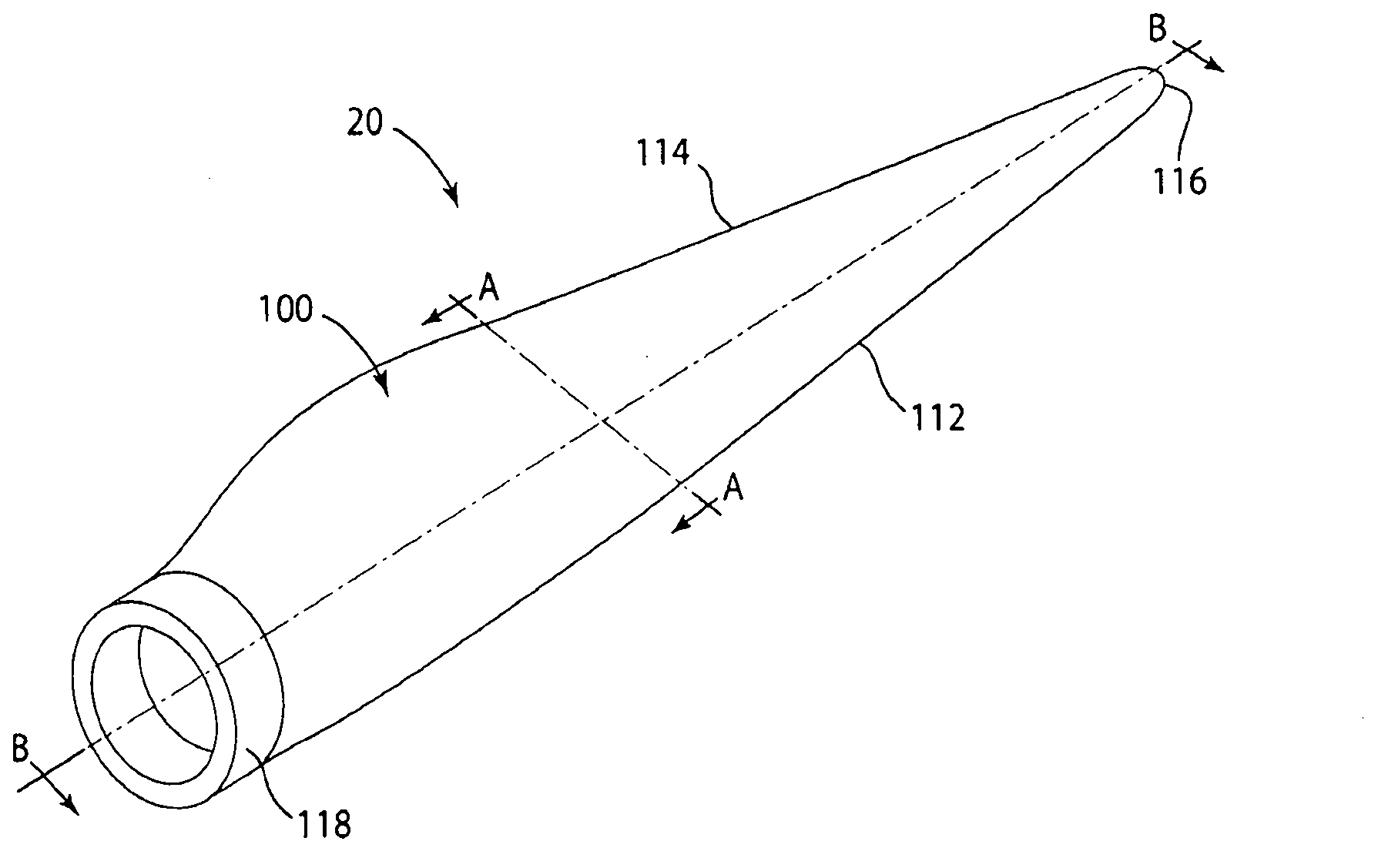
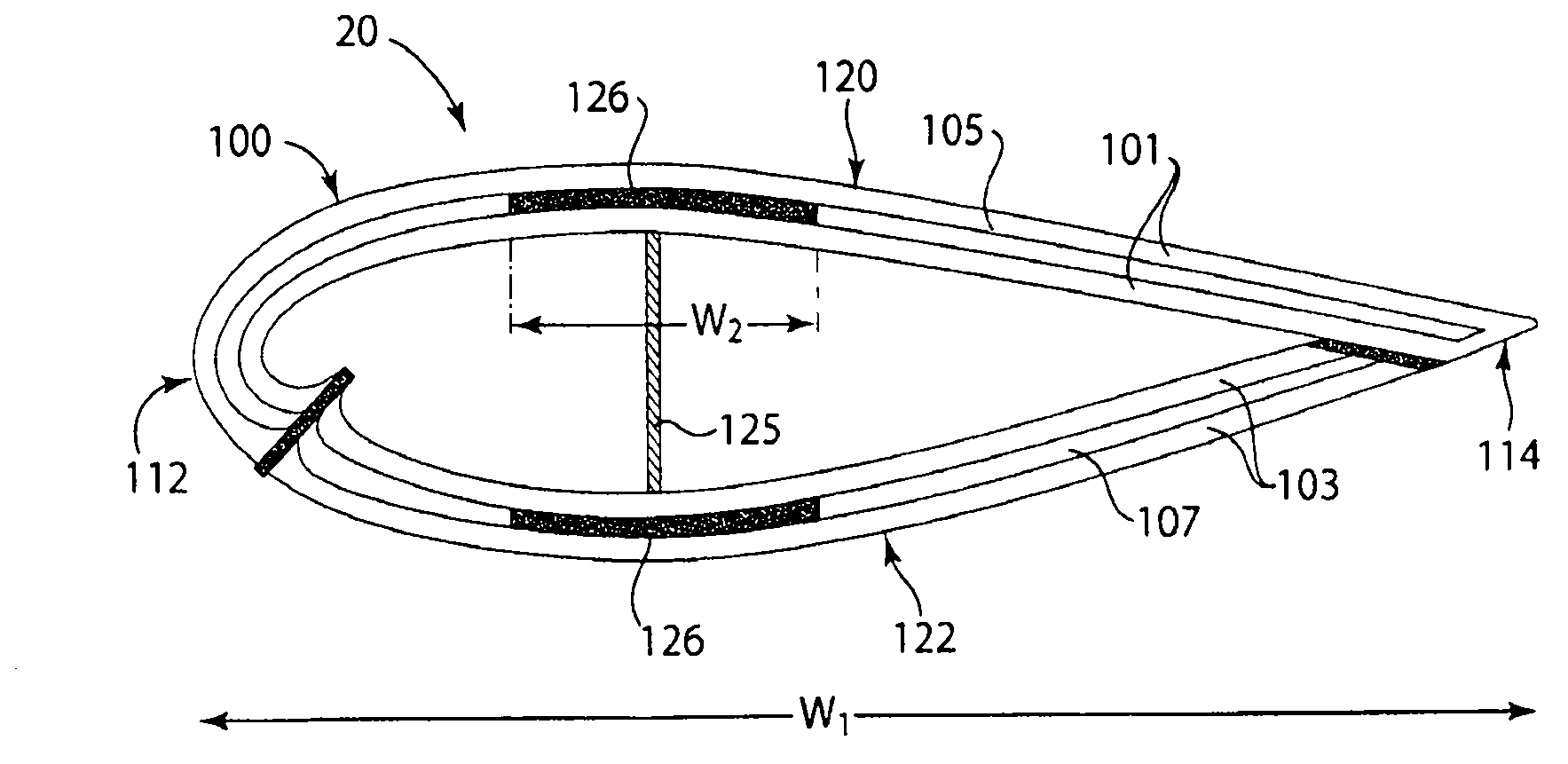
[0063] Such as figure 2 As shown in, the turbine blade 20 includes an airfoil section 100 that extends between the tip 116 and the root 118 of the blade. The airfoil portion 100 defines the front edge 112 and the rear edge 114 of the blade 20. The root 118 is co...


PUM


Abstract

Structural preform layers (300a, 300b, 400) of multiple rigid unidirectional strength elements or rods (202, 402) are constructed and arranged for use in fabricating load-bearing support structures and reinforcements of wind turbine blades. Individual preform layers include multiple elongate unidirectional strength elements or rods arranged in a single layer along a longitudinal axis of the preform layer. Each preform layer includes one or more fibrous carrier layers (312) to which the multiple strength elements or rods are joined and arranged in the single layer. Each strength element or rod is longitudinally oriented and adjacent to other elements or rods. Individual strength elements or rods include a mass of substantially straight unidirectional structural fibers embedded within a matrix resin such that the elements or rods have a substantially uniform distribution of fibers and high degree of fiber collimation. The relative straightness of the fibers and fiber collimation provide strength elements or rods and the preform layers with high rigidity and significant compression strength.

Description

[0001] Related application [0002] This non-provisional patent application claims priority from U.S. Provisional Patent Application No. 61 / 295,006 filed on January 14, 2010, the disclosure of which is incorporated herein by reference. Technical field [0003] The present invention generally relates to wind turbine rotor blades. The invention also relates to structural pre-formed layers of multiple strength elements or rods used to manufacture wind turbine blade components. Background technique [0004] Technological advancements in wind turbines continue to prove that energy from wind provides a commercially available alternative energy source. Design improvements allow the size of wind turbines and rotor blades to be increased in order to achieve an increase in energy output. However, manufacturing cost is a problem for the development of wind energy technology into a competitive alternative energy source. In particular, factors affecting the manufacturing cost and energy effic...

Claims


Application Information

Patent Timeline
IPC IPC(8): F03D3/06F03D11/00B29C70/54B29C70/20B29B11/16
CPCB29D99/0028Y02E10/722Y02E10/721F03D3/062B29C70/083F03D1/0675F03D11/00B29L2031/085B29C70/023B29B11/16Y02E10/74F03D80/00F03D9/25Y10T156/10F05B2220/30F05B2230/20F05B2240/2211F05B2280/6003Y02E10/72Y02P70/50Y10T29/49337Y10T29/4979Y10T29/49787Y10T29/49632B23P15/04
Inventor J·D·格鲁恩E·富兰克林K·那拉西莫罕
Owner SIEMENS GAMESA RENEWABLE ENERGY SERVICE GMBH
Why Eureka
Eureka Blog
Learn More