Hydrodynamic torque converter

一种液力变矩器、变矩器的技术,应用在弹簧/减震器、流体传动装置、振动抑制调整等方向,能够解决扭振阻尼器阻尼性能不令人满意等问题

Inactive Publication Date: 2012-10-31
SCHAEFFLER TECH AG & CO KG
View PDF4 Cites 14 Cited by
  • Summary
  • Abstract
  • Description
  • Claims
  • Application Information

AI Technical Summary

Problems solved by technology

Under certain circumstances and requirements for the torque converter, the damping performance of the torsional vibration damper is unsatisfactory

Method used


Image

  • Hydrodynamic torque converter
  • Hydrodynamic torque converter
  • Hydrodynamic torque converter

Examples


Embodiment Construction

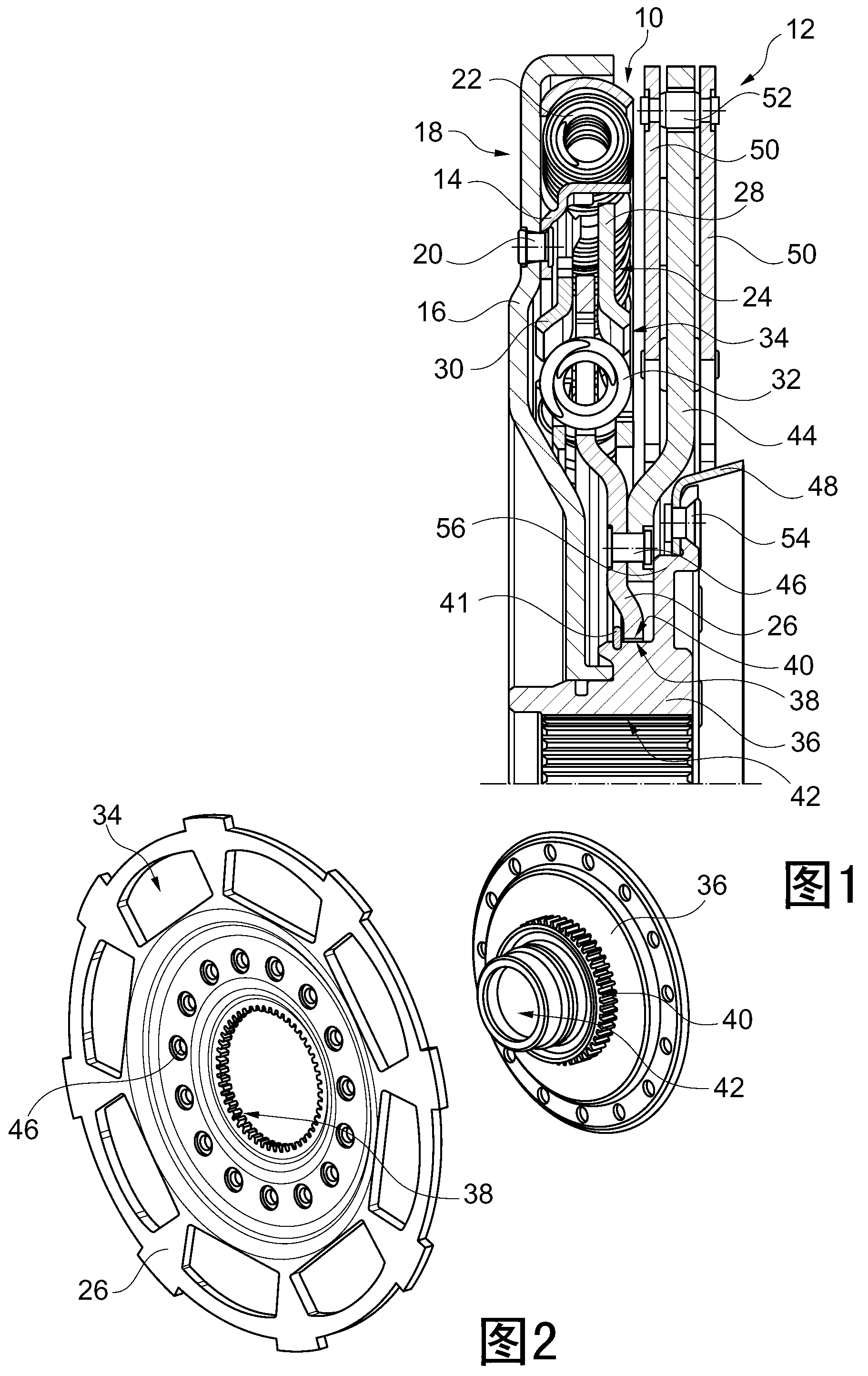
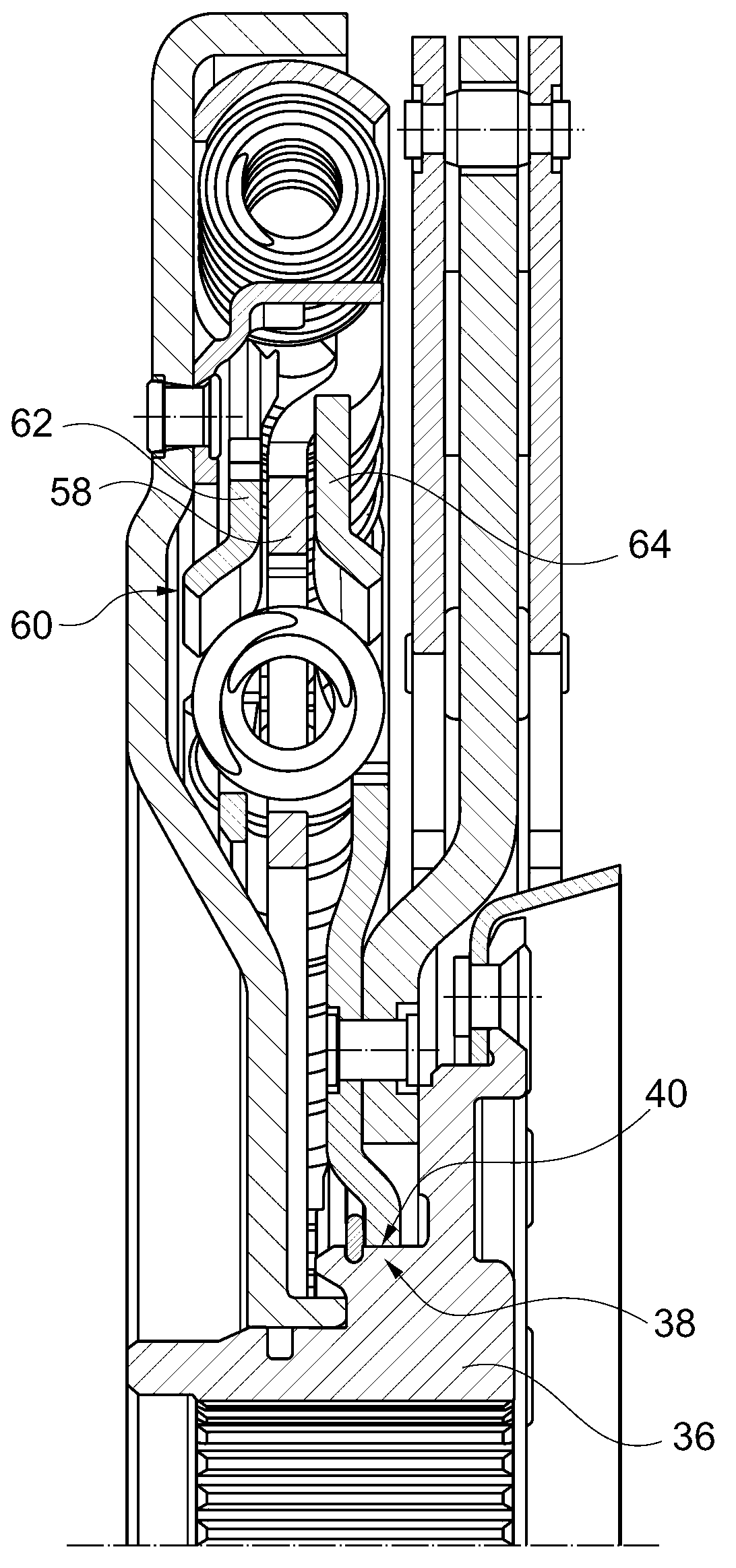
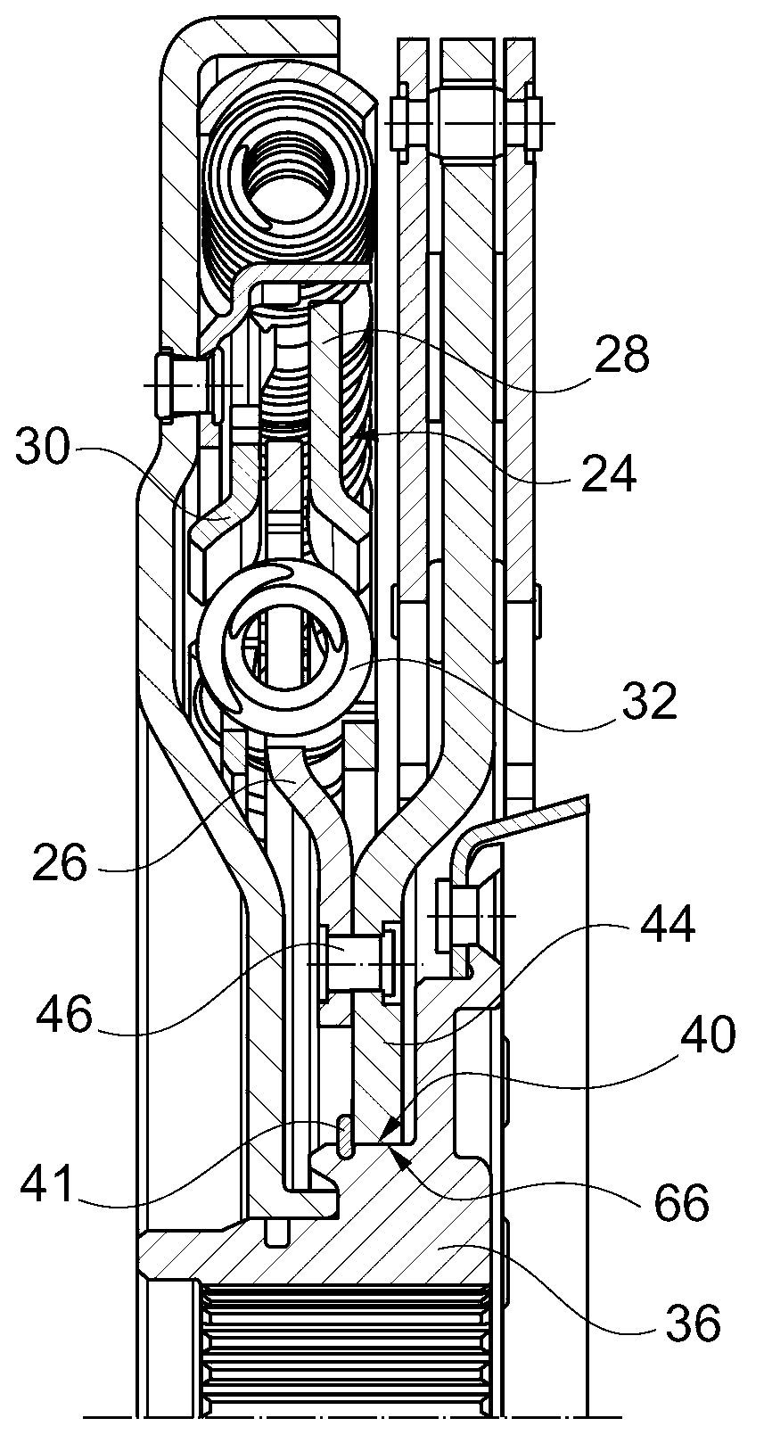
[0018] figure 1 shows a cross-sectional view of a torque converter according to an embodiment of the present invention, additionally figure 2 Shows damper output section and output hub in perspective view. The sectional illustration shows a torsional vibration damper 10 and a centrifugal pendulum device 12 arranged inside the torque converter housing and formed as a series damper. The damper output part 14 of the torsional vibration damper 10 is non-rotatably connected to the clutch output 16 of the torque converter bridge clutch 18 via a riveting element 20 . The damper input part 14 is now connected via a radially outer first energy storage element 22 to a damper middle part 24 , which is rotatable to a limited extent relative to the damper input part 14 . The damper middle part 24 surrounds the first energy storage element 22, such as a bow spring, to secure it radially and axially. The first energy storage element 22 applies a load to the first outer peripheral side th...


PUM


Abstract

Hydrodynamic torque converter comprising a torque converter lock-up clutch (18) and a converter housing connected thereto at the input side and a pump wheel non-rotationally connected thereto, a turbine (48) connected to an output hub (36) at the output side for conjoint rotation and a torsional vibration damper (10) operatively arranged between the clutch output (16) of the torque converter lock-up clutch (18) and the output hub. The torque converter further comprises a centrifugal pendulum device (12) which is arranged inside the converter housing and which comprises a pendulum flange (44) with pendulum weights (50) that can move thereon in a pendulum fashion to a limited extent. The pendulum flange (44) is arranged axially between the torsional vibration damper (10) and the turbine (48) and is connected to a damper output part (26, 60) of the torsional vibration damper (10) for conjoint rotation. The damper output part and / or the pendulum flange can be directly connected to the output hub (36) by means of a form-locking connection.

Description

technical field [0001] The invention relates to a hydrodynamic torque converter having the features stated in the preamble of claim 1 . Background technique [0002] A torque converter of this type can be arranged, for example, in a drive train of a motor vehicle for torque transmission between the internal combustion engine and the transmission. Such a torque converter has a pump wheel connected to the drive side, which influences the fluid flow in the direction of the turbine connected to the output side and can thus drive it. Before the fluid flows back from the turbine into the pump wheel, it passes a guide wheel and thus undergoes a change in the flow direction under certain circumstances, which affects the torque transmission between the pump wheel and the turbine wheel . [0003] As is known, a torque converter bridge clutch is arranged in the torque converter to bypass the fluid influenced fluid torque transfer. The lock-up clutch thus connects the drive side, for...

Claims


Application Information

Patent Timeline
Patent Type & Authority Applications(China)
IPC IPC(8): F16F15/14
CPCF16H2045/0263F16H2045/0231F16F15/145Y10T74/2128
Inventor S·迈恩沙因P·德罗尔
Owner SCHAEFFLER TECH AG & CO KG
Why Eureka
Try Eureka