Differential air-pressure spray dust removing system and implementation method thereof

A technology for dust removal system and realization method, applied in the direction of separation method, chemical instrument and method, use of liquid separation agent, etc., can solve the problems of high cost, complex structure of dust removal system, no collection and combined use of rainwater utilization, etc., to reduce energy consumption consumption effect

Inactive Publication Date: 2012-11-07
吴英戈
View PDF3 Cites 8 Cited by
  • Summary
  • Abstract
  • Description
  • Claims
  • Application Information

AI Technical Summary

Problems solved by technology

However, the traditional dust removal system is not only complex in structure and high in cost, but also requires an external power supply as the power supply of the dust removal system, which increases the local financial burden and is difficult to be widely used in public places
Both of the above-mentioned facilities or equipment have great limitations, as well as the defects of waste of resources, and there is no precedent in the prior art that combines the use of potential energy collection and rainwater utilization attenuation in public places

Method used


Image

  • Differential air-pressure spray dust removing system and implementation method thereof
  • Differential air-pressure spray dust removing system and implementation method thereof
  • Differential air-pressure spray dust removing system and implementation method thereof

Examples


Embodiment 1

[0038] At present, the dust removal and cooling systems used in highway construction and urban construction are very complex in structure, and require an external power supply or other power source to provide power for the dust removal system to make the dust removal system work. The cost is not only high, but also the daily maintenance is very high. Inconvenience; and for speed bumps used in highways and communities, motorized and non-motor vehicles will lose part of their power potential energy after decelerating through the speed bumps. After the lost power potential energy is transmitted to the ground, it gradually disappears and is not effectively used. After considering the existing technology of the above two equipment or facilities, the invention designed a new type of dust removal system combining the two through creative work.

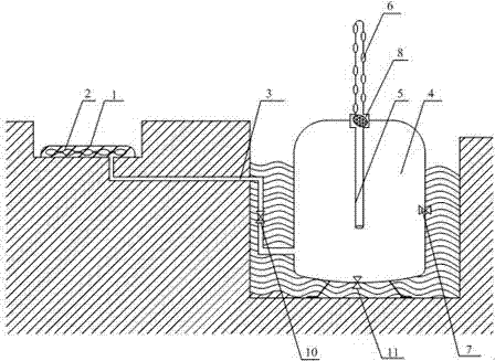
[0039] Such as figure 1 As shown, the differential air spray dust removal system is mainly composed of a speed belt 1 installed on the road, a n...

Embodiment 2

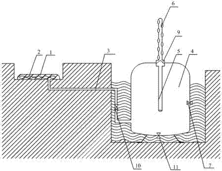
[0047] Such as figure 2 As shown, the difference between this embodiment and embodiment 1 is that the diffusion chamber in the pressure release unit is provided with a safety valve 9, which unilaterally opens outwards through the air pressure difference between the tank and the outside, and only allows water flow and air pressure Flow to the upper end of the guide tube 5.

Embodiment 3

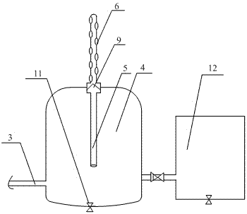
[0049] Such as Figure 4 As shown, the difference between this embodiment and Embodiment 1 is that a sedimentation filter tank 12 is added, and the sedimentation filter tank 12 is connected to the water storage pressure tank 4, which can be used to store water on the one hand, and then remove the water. Sedimentation filtration makes the water sprayed by the dust removal system cleaner and environmentally friendly; on the other hand, adding water to the sedimentation filter tank can ensure that the dust removal system can work normally at any time, avoiding the defects of insufficient precipitation in the area that affect the dust removal operation of the dust removal system.


PUM


Abstract

The invention discloses a differential air-pressure spray dust removing system and solves the problems that power potential energy losing after deceleration of motorized or non-motorized objects by deceleration strips or public place buffering is not utilized effectively, current dust removing systems are complicated in structure, high in cost, need external power supplies or other power supplies in the prior art. The spray dust removing system comprises a deceleration strip, air sacs, a water and pressure storage device, and a spray actuation mechanism. The air sacs are disposed in the deceleration strip or a public passage. The water and pressure storage device is communicated with the air sacs through an air guide tube. The spray actuation mechanism is disposed on the water and pressure storage device. The water and pressure storage device mainly comprises a water and pressure storage tank. The spray actuation mechanism comprises a flow guide tube. The lower end of the flow guide tube penetrates into the water and pressure storage tank. The upper end of the flow guide tube is located outside the water and pressure storage tank. A spray nozzle is disposed at the upper end of the flow guide tube. The invention further discloses an implementation method of the spray dust removing system. The spray dust removing system is simple in structure, convenient to implement, energy-saving and environment-friendly.

Description

Technical field [0001] The invention relates to the field of environmental protection and dust removal, in particular, is an automatic spray removal system that uses air pressure difference to realize pressure control and fully collects and utilizes physical power and natural precipitation lost in public places. Background technique [0002] Speed ​​bumps are also called deceleration ridges, which are traffic facilities installed on highways to slow down vehicles passing by. They are generally strip-shaped or point-shaped. The material is mainly rubber or metal; they are mainly used in highway crossings, industrial and mining enterprises, schools , Residential quarters and other places, to slow down the speed of motor vehicles, non-motor vehicles and special traffic safety settings. Vehicles passing through the deceleration belt will lose part of the power potential energy to achieve the purpose of deceleration, and this part of the lost potential energy is currently not fully ut...

Claims


Application Information

Patent Timeline
Patent Type & Authority Applications(China)
IPC IPC(8): B01D47/06E01F9/047E01F9/529
Inventor 吴英戈何静岑朴素蒋成素
Owner 吴英戈
Why Eureka
Try Eureka