Core mold and shaping method for shaping strip annular internal reinforced rib rotary body thin-wall part

A technology of internal reinforcement and revolving body, used in metal processing equipment, manufacturing tools, forging/pressing/hammer devices, etc.

Inactive Publication Date: 2012-11-07
NORTHWESTERN POLYTECHNICAL UNIV
View PDF12 Cites 12 Cited by
  • Summary
  • Abstract
  • Description
  • Claims
  • Application Information

AI Technical Summary

Problems solved by technology

[0004] However, when the rotary forging method is used to form the thin-walled rotary body with annular inner ribs, the demoulding problem at the inner ribs becomes t

Method used


Image

  • Core mold and shaping method for shaping strip annular internal reinforced rib rotary body thin-wall part
  • Core mold and shaping method for shaping strip annular internal reinforced rib rotary body thin-wall part
  • Core mold and shaping method for shaping strip annular internal reinforced rib rotary body thin-wall part

Examples


Embodiment 1

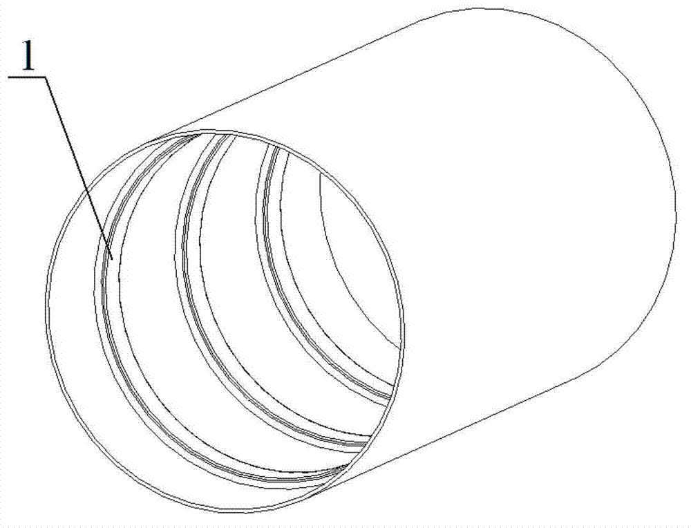
[0036]This embodiment is a forming process of a thin-walled part of a rotating body with an annular inner reinforcing rib, and mainly designs a core mold for forming a thin-walled part of a rotating body with an annular inner reinforcing rib.

[0037] The geometric shape of the thin-walled part of the rotary body with the annular internal reinforcement described in this embodiment is as follows: figure 1 As shown, the inner diameter is 300mm, the axial length is 500mm, and the wall thickness is 10mm. The inner wall has three annular inner ribs 1 with a width of 50mm and a height of 5mm along the axial direction, and the distance between them is 100mm. The distance between the end faces is 75mm.

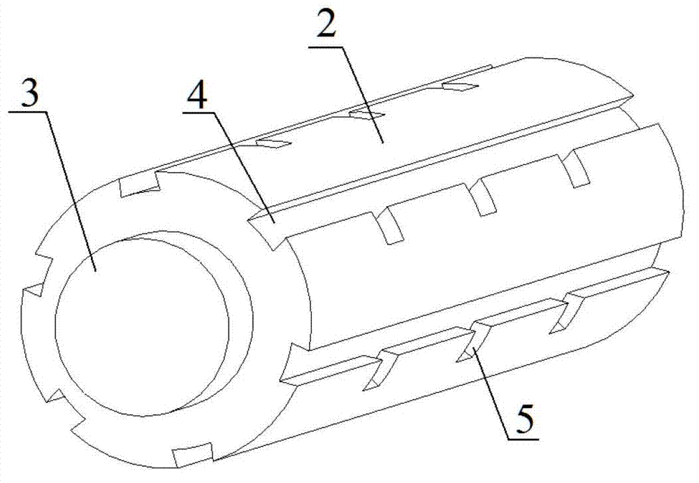
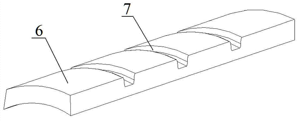
[0038] The core mold for forming the above-mentioned rotating thin-walled part proposed in this embodiment includes a base mold 9 , a shape mold 10 and a fixing pin 11 .

[0039] Base mold 9 is made of die steel 4CrMnSiMoV, which consists of base mold main body 2 and draft end 3. Th...

Embodiment 2

[0052] This embodiment is a forming process of a thin-walled part of a rotating body with an annular inner reinforcing rib, and mainly designs a core mold for forming a thin-walled part of a rotating body with an annular inner reinforcing rib.

[0053] The geometrical shape of the thin-walled part of the rotary body to be formed with the annular inner reinforcing rib described in this embodiment is as follows: the inner diameter is 100mm, the axial length is 200mm, the wall thickness is 5mm, and the inner wall has three annular inner reinforcements with a width of 20mm and a height of 3mm along the axial direction. The distance between the ribs is 40mm, and the distance between the inner ribs at both ends and the two ends of the thin-walled part of the rotating body is 30mm.

[0054] The core mold for forming the above-mentioned rotating thin-walled part proposed in this embodiment includes a base mold 9 , a shape mold 10 and a fixing pin 11 .

[0055] Base mold 9 is made of d...


PUM

PropertyMeasurementUnit
Top widthaaaaaaaaaa
Diameteraaaaaaaaaa
Axial lengthaaaaaaaaaa

Abstract

The invention relates to a core mold and a shaping method for a shaping strip annular internal reinforced rib rotary body thin-wall part, wherein a base mold is composed of a base mold main body and a mold withdrawing end; a swallow tail groove and a positioning groove are formed on the base mold main body; a shape mold is wholly of an annular structure; the shape mold is uniformly divided into a plurality of split molds of same shapes; shaping arc grooves for annular internal reinforced ribs are formed on the shaping plane of the split molds; swallow tail tenons matched with the wallow tail groove and the positioning groove are formed on the inner surfaces of the split molds. By adopting the mode of combined core mold, the problem of hard demolding during the shaping process of the rotary body thin-wall part internal reinforced rib is solved. By virtue of the positioning on the base mold swallow tail groove, the movement of the shaping mold is prevented effectively; and the shaping precision of the rotary body thin-wall part internal reinforced rib is improved. The base mold, the shaping mold and the fixing pin of the core mold can be made of different metal materials according to respective strength requirements; only the mold needs to be replaced for rotary body thin-wall pieces of which the inner diameters are the same and the internal reinforcing ribs are different, so that the cost of the mold is reduced greatly.

Description

technical field [0001] The invention relates to a technical method for forming a thin-walled part of a rotary body by rotary forging, in particular to a core mold and a forming method for forming a thin-walled part of a rotary body with annular inner reinforcement ribs. Background technique [0002] With the development of science and technology, the production of parts of high-end technical equipment has higher and higher requirements for material forming. In the field of aerospace and weapon industry, the thin-walled complex parts of the rotating body are widely used in aero engine covers, integral rocket engine components, artificial satellites, etc. In order to improve the service strength and service life of the thin-walled complex parts of the rotating body, usually Forming a ring-shaped reinforcing rib, the design of this rib greatly improves the quality level of the thin-walled complex parts of the rotating body. However, due to the constraints of the current forming...

Claims


Application Information

Patent Timeline
IPC IPC(8): B21J13/02
Inventor 李江李付国张明杰王瑞亭
Owner NORTHWESTERN POLYTECHNICAL UNIV
Why Eureka
Try Eureka