Damping type automatic -passing phase separation switching device for electrified railways
An electrified railway, automatic switching technology, applied in power lines, transportation and packaging, vehicle components, etc., can solve problems affecting equipment life, arcing, transient voltage generation, etc., to extend service life, reduce impact, and use long life effect
- Summary
- Abstract
- Description
- Claims
- Application Information
AI Technical Summary
Problems solved by technology
Method used
Image

Examples
specific Embodiment approach
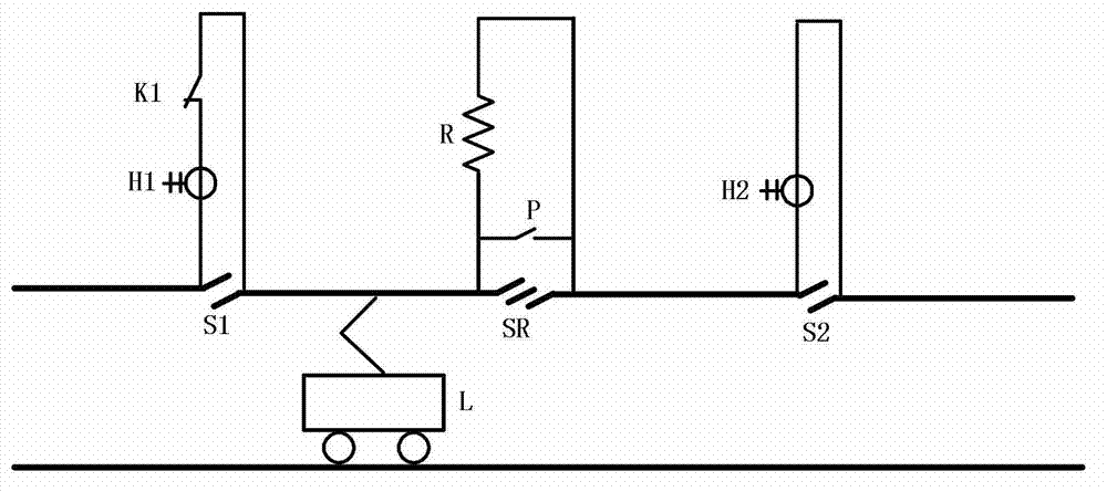
[0032] figure 1 As shown, a specific embodiment of the present invention is: a damping type automatic switching over-phase splitting device for electrified railway, which consists of:
[0033] The gap S1 between the neutral section and the catenary-A bridges the high-voltage switch K1 with the current transformer-H1; the neutral section is provided with an insulation segment gap SR, and the insulation segment gap SR bridges the resistor R; The gap S2 between the neutral section and catenary II B bridges the current transformer II H2;
[0034] The output terminal of current transformer one H1, the output terminal of current transformer two H2 and the control terminal of high voltage switch one K1 are all connected to the measurement and control unit.
[0035] In this example, a bypass switch P is connected across the resistor R.
[0036] This embodiment is applicable to the situation where the train L passes in one direction from catenary one A to catenary two B (such as upli...
Embodiment 2
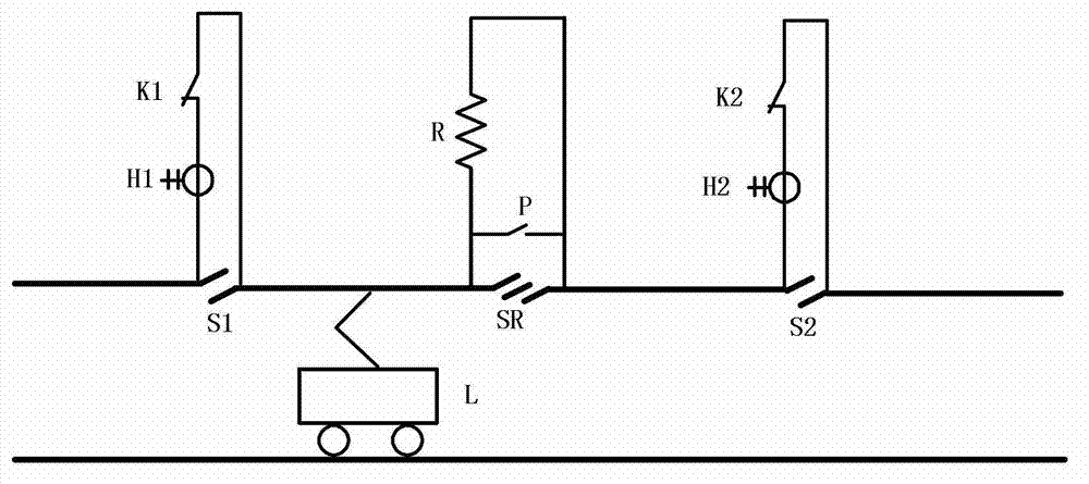
[0038] figure 2 It shows that the structure of this example is basically the same as that of Embodiment 1, the only difference is that the gap S2 between the neutral section and the catenary 2B bridges the high-voltage switch 2 K2, and the current transformer 2 H2 is a part of the high-voltage switch 2 K2. Current Transformer.
[0039] This example is applicable to the situation that the train L passes through the single-track railway in both directions.
Embodiment 3
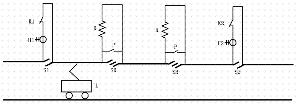
[0041] image 3It shows that the structure of this example is basically the same as that of the second embodiment, the only difference is that there are two insulating segment gaps SR set on the neutral section, and each insulating segment gap SR is connected across the resistor R .
[0042] The rated voltage of high-voltage switch one K1 and high-voltage switch two K2 of the present invention is 27.5kV, and the rated current is the rated current of the train; the rated voltage of resistor R is 27.5kV, and the resistance value of resistor R is usually 10-505kΩ, the specific value It is determined by its damping effect and minimum loss. For example, the resistance value of 1 ampere current is selected under the corresponding voltage: when it is used for the different-phase electric splits at the outlet of the traction substation, the rated voltage of the electric split phases is 27.5kV, then the resistance The resistance value of the resistor R is 27.5kΩ. When it is used in th...
PUM
 Abstract
Description
Claims
Application Information
 - R&D
- Intellectual Property
- Life Sciences
- Materials
- Tech Scout
- Unparalleled Data Quality
- Higher Quality Content
- 60% Fewer Hallucinations
Browse by: Latest US Patents, China's latest patents, Technical Efficacy Thesaurus, Application Domain, Technology Topic, Popular Technical Reports.
© 2025 PatSnap. All rights reserved.Legal|Privacy policy|Modern Slavery Act Transparency Statement|Sitemap|About US| Contact US: help@patsnap.com