Oil heater and welding method thereof

An oil heater and welding method technology, applied in welding equipment, metal processing equipment, transportation passenger cars, etc., can solve the problems of more than 60 decibels, actual temperature deviation, high temperature, and achieve the effect of good uniformity

Active Publication Date: 2012-11-07
宁波联合华发五金机械有限公司
View PDF12 Cites 1 Cited by
  • Summary
  • Abstract
  • Description
  • Claims
  • Application Information

AI Technical Summary

Problems solved by technology

[0002] At present, the heating devices of the oil heaters in the prior art are all directly welded to the bottom of the tank body. During use, when the heating device starts to heat, the heating device is in partial contact with the bottom surface of the tank body directly, so that The heat generated by the heating device raises the position where the bottom of the tank body contacts the heating device first, and then spreads to other positions at the bottom of the tank body. This has the problem of high temperature at the bottom of the tank body, which in turn makes the oil in the tank body It will make a loud sound when heating, and the volume generally exceeds 60 decibels; at the same time, there is a large deviation between the temperature measured by the temperature controller and the actual temperature of the oil.

Method used


Image

  • Oil heater and welding method thereof
  • Oil heater and welding method thereof
  • Oil heater and welding method thereof

Examples


Embodiment 1

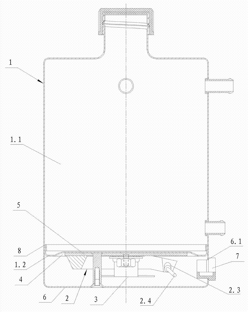
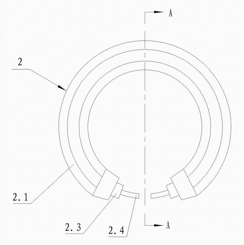
[0034] Such as figure 1 , figure 2 , image 3 , Figure 4 and Figure 5 The shown oil heater includes a tank body 1, a heating device 2 and a temperature controller 3 (of course, it also includes other components, but since it does not involve the invention of the present invention, it will not be repeated here), The heating device 2 and the temperature controller 3 are all connected to the bottom surface of the tank body 1, the bottom surface of the tank body 1 is provided with a groove 4, and the heating device 2 and the temperature controller 3 are all located in the groove 4 Inside, and between the heating device 2 and the bottom surface of the groove 4, a heat conduction plate 5 is provided, the shape of the heat conduction plate 5 is the same as that of the bottom surface of the groove 4, and a plane of the heat conduction plate 5 is completely attached to the bottom surface of the groove 4 , the heating device 2 and the temperature controller 3 are connected to the...

Embodiment 2

[0052] Such as Figure 6 and Figure 7 A kind of oil heater shown, it comprises tank body 1, heating device 2 and temperature controller 3, described heating device 2 and temperature controller 3 are all connected to the bottom surface of tank body 1, the tank body 1 The bottom surface is provided with a groove 4, the heating device 2 and the temperature controller 3 are located in the groove 4, and a heat conducting plate 5 is arranged between the heating device 2 and the bottom surface of the groove 4, and the heat conducting plate 5 The shape is the same as that of the bottom surface of the groove 4. One plane of the heat conduction plate 5 is completely attached to the bottom surface of the groove 4. The heating device 2 and the temperature controller 3 are connected to the other plane of the heat conduction plate 5, and the temperature must be ensured during installation. The probe of the controller 3 is attached to the heat conducting plate 5.

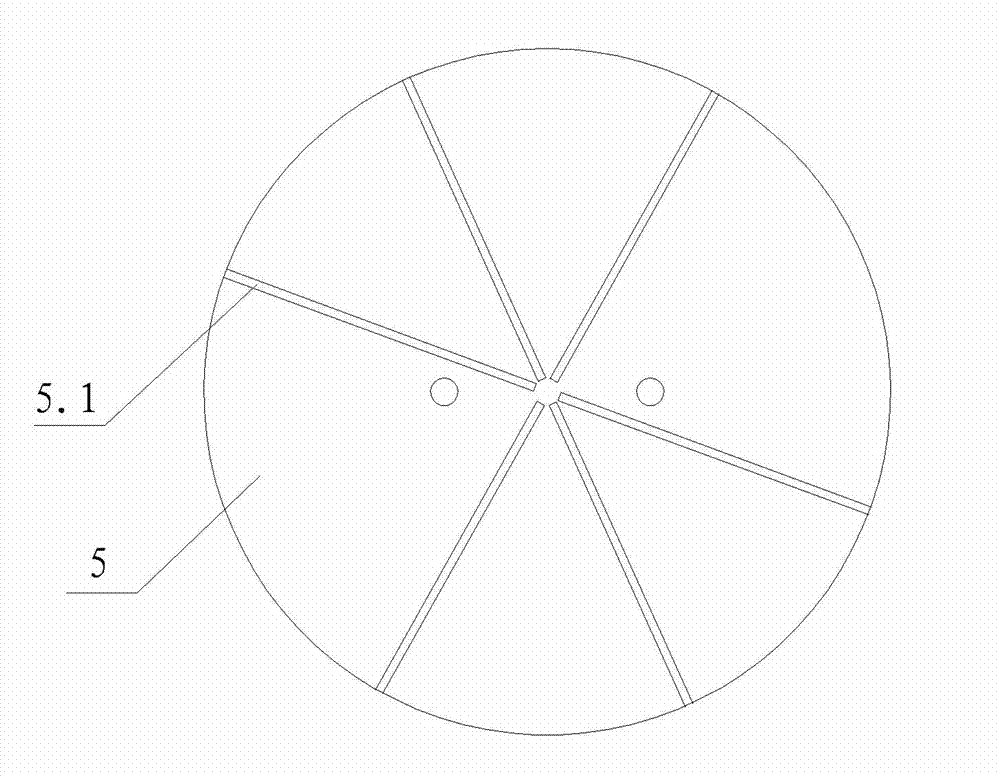
[0053] Eight radial air...

Embodiment 3

[0070]An oil heater, which includes a tank body 1, a heating device 2 and a temperature controller 3, the heating device 2 and the temperature controller 3 are connected to the bottom surface of the tank body 1, and the bottom surface of the tank body 1 is set There is a groove 4, the heating device 2 and the temperature controller 3 are located in the groove 4, and a heat conducting plate 5 is arranged between the heating device 2 and the bottom surface of the groove 4, and the shape of the heat conducting plate 5 is the same as The shape of the bottom surface of the groove 4 is the same, one plane of the heat conduction plate 5 is completely attached to the bottom surface of the groove 4, the heating device 2 and the temperature controller 3 are connected to the other plane of the heat conduction plate 5, and the temperature controller must be ensured during installation. The probe of 3 is attached to the heat conducting plate 5.

[0071] Four radial air guide grooves 5.1 ar...


PUM


Abstract

The invention discloses an oil heater. A heating device (2) and a temperature controller (3) are connected to the bottom surface of a tank body (1); a groove (4) is arranged on the bottom surface of the tank body (1); the heating device (2) and the temperature controller (3) are located in the groove (4); a heat conducting plate (5) is arranged between the heating device (2) and the bottom surface of the groove (4); the shape of the heat conducting plate (5) is the same as that of the bottom surface of the groove (4); one plane of the heat conducting plate (5) is completely fitted with the bottom surface of the groove (4); and the heating device (2) and the temperature controller (3) are connected to the other plane of the heat conducting plate (5). The welding method of the oil heater comprises the following steps for welding the heating device (2) and the heat conducting plate (5): 1) preparing base solution and dry powder; 2) applying the base solution; 3) sprinkling the dry powder on the base solution; 4) turning on a soldering machine and preheating a cushion block of the soldering machine; 5) putting the heating device (2) and the heat conducting plate (5) on the cushion block; 6) pressing the heating device (2) and the heat conducting plate (5); and 7) applying gypsum paste. Compared with the prior art, the oil heater disclosed by the invention has the characteristics that the sound is lower during heating and the difference between the temperature measured by the temperature controller and the actual temperature of the oil is smaller.

Description

technical field [0001] The invention belongs to the field of heating equipment, in particular to an oil heater and a welding method thereof. Background technique [0002] At present, the heating devices of the oil heaters in the prior art are all directly welded to the bottom of the tank body. During use, when the heating device starts to heat, the heating device is in partial contact with the bottom surface of the tank body directly. The heat generated by the heating device raises the position where the bottom of the tank body contacts the heating device first, and then spreads to other positions at the bottom of the tank body, which causes the problem that the temperature at the bottom of the tank body is relatively high, which in turn makes the oil in the tank body It will make a loud sound when heating, and the volume generally exceeds 60 decibels; at the same time, there is a large deviation between the temperature measured by the temperature controller and the actual t...

Claims


Application Information

Patent Timeline
IPC IPC(8): B65D88/74B23K1/00
Inventor 李启泽
Owner 宁波联合华发五金机械有限公司
Why Eureka
Try Eureka