Rotary compressor

A technology of rotary compressors and compression mechanisms, applied in the direction of rotary piston machinery, rotary piston pumps, mechanical equipment, etc., can solve the problems of processing difficulty, cost increase, and insufficient effect, and achieve simple and reasonable structure and wide application range Wide range and high energy efficiency ratio

Inactive Publication Date: 2012-11-07
GUANGDONG MEIZHI COMPRESSOR
View PDF9 Cites 13 Cited by
  • Summary
  • Abstract
  • Description
  • Claims
  • Application Information

AI Technical Summary

Problems solved by technology

However, the effects of these two methods are not good enou

Method used


Image

  • Rotary compressor
  • Rotary compressor
  • Rotary compressor

Examples


no. 1 example

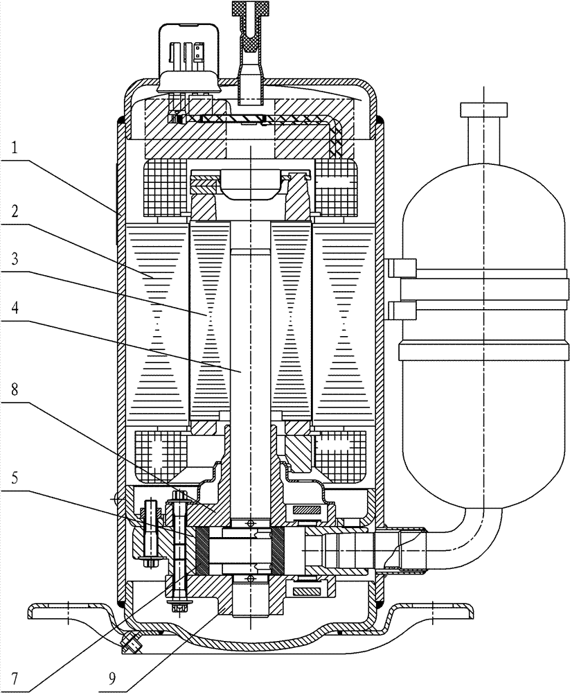
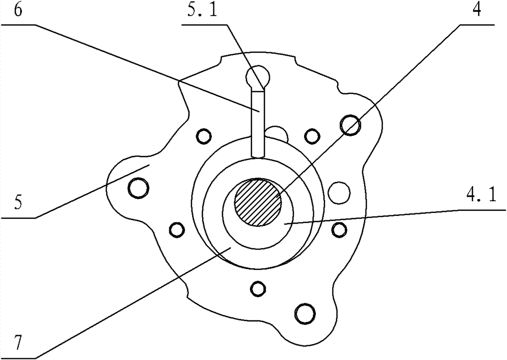
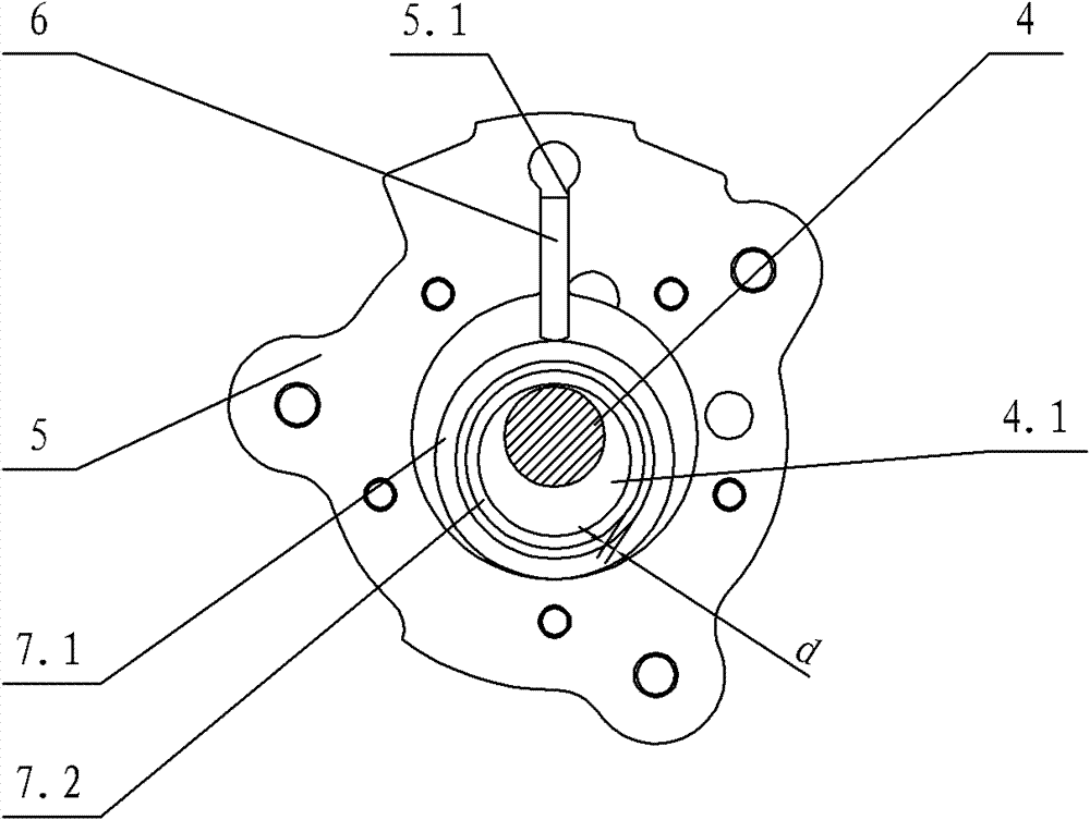
[0022] see image 3 , the rotary compressor includes a housing 1, a motor and a compression mechanism are arranged in the housing 1; the motor includes a stator 2 and a rotor 3, the stator 2 is fixed to the inner wall of the housing 1, and the rotor 3 is connected to the crankshaft 4 in the compression mechanism Connected, the compression mechanism also includes a cylinder 5, the cylinder 5 is provided with a slide groove 5.1 for accommodating the slide 6 and a piston that is sleeved on the outer circumference of the eccentric shaft 4.1 of the crankshaft 4 and rotates with the crankshaft 4 to compress the refrigerant, and the slide The front end of 6 is in contact with the outer circumference of the piston. The main bearing 8 and auxiliary bearing 9 for supporting the crankshaft 4 are arranged on the upper and lower sides of the cylinder 5. The piston includes a large piston ring 7.1 and a small piston ring 7.2 arranged concentrically, and a small piston ring 7.2 Set on the ou...

no. 2 example

[0026] see Figure 4 , In this embodiment, the front end of the sliding plate 6 is provided with a needle roller 6.1, and the needle roller 6.1 is in contact with the outer periphery of the large piston ring 7.1.

[0027] The purpose of this embodiment is to change the sliding friction between the front end of the sliding plate and the outer periphery of the large piston ring 7.1 into rolling friction, but there is a problem here. If the existing rotary compressor design of one piston is adopted, this method cannot achieve the desired result. Effect, because the relative linear velocity between the existing piston and the front end of the slider is very high, and the outer circumference of the needle roller is limited by the width of the front end of the slider, so that the speed of the needle roller rotation is too high, resulting in The power consumption loss of the rotation of the needle roller is worsened, and the reliability of the needle roller is reduced; because this t...

no. 3 example

[0030] see Figure 5-Figure 6 , In this embodiment, a groove 7.11 is provided on the outer periphery of the large piston ring 7.1, and the front end of the sliding plate 6 is embedded in the groove 7.11.

[0031] In this embodiment, the front end of the sliding plate is nested in the groove 7.11 on the outer circumference of the large piston ring 7.1. The purpose of this design is to make the sliding plate follow the large piston ring 7.1, and there is no high speed between the two. At the same time, the front end of the sliding plate is in close contact with the large piston ring 7.1, and the refrigerant leakage at the contact point can be optimized, thus improving the energy efficiency of the compressor. To the expected effect, because there is no relative sliding between the single piston and the sliding plate, the single piston has no self-rotation, and the linear velocity between the inner circumference of the single piston and the eccentric shaft of the crankshaft will b...


PUM


Abstract

A rotary compressor comprises a housing. A motor and a compressing mechanism are arranged in the housing. The motor comprises a stator and a rotor. The stator is fixedly connected with the inner wall of the housing. The rotor is connected with a crankshaft in the compressing mechanism. The compressing mechanism also comprises a cylinder. A slide plate chute for holding a slide plate and a piston which is sleeved on the periphery of an eccentric shaft of the crankshaft and rotates together with the crankshaft to compress a refrigerant are arranged in the cylinder. The front end of the slide plate contacts with the periphery of the piston. A base bearing and an auxiliary bearing which are used for supporting the crankshaft are arranged at upper and lower sides of the cylinder. The piston comprises a large piston ring and a small piston ring which are concentrically arranged, wherein the small piston ring is sleeved on the periphery of the eccentric shaft; the large piston ring is sleeved on the periphery of the small piston ring; the inner circumference of the large piston ring is in clearance fit with the periphery of the small piston ring and the fit clearance is less than or equal to 40m. The rotary compressor provided by the invention has characteristics of simple and reasonable structure, flexible operation, low manufacturing cost, small frictional power consumption, high energy efficiency ratio and wide application range.

Description

technical field [0001] The present invention relates to a rotary compressor. Background technique [0002] For rotary compressors, especially rolling rotor rotary compressors, improving energy efficiency has always been an important issue. For mechanical friction power consumption, the general method is to reduce the roughness of the friction surface or increase the lubricating oil on the friction surface. The method either brings about an increase in the processing cost and is difficult to achieve; or the effect is not ideal. [0003] Existing rotary compressors, see attached figure 1 - attached figure 2 , the sealed housing 1 is provided with a motor and a compression mechanism; the motor includes a stator 2 and a rotor 3, the stator 2 is fixed to the inner wall of the housing 1, the rotor 3 is connected to the crankshaft 4 in the compression mechanism, and the compression mechanism also includes a cylinder 5. Cylinder 5 has slide slot 5.1, inside slide slot 5.1 there ...

Claims


Application Information

Patent Timeline
IPC IPC(8): F04C18/356
Inventor 李华明
Owner GUANGDONG MEIZHI COMPRESSOR
Why Eureka
Try Eureka