Transmission device for optical equipment

A transmission device and equipment technology, applied in the direction of transmission device, optics, optical components, etc., can solve the problems of affecting imaging and inaccurate travel.

Active Publication Date: 2012-11-07
ASIA OPTICAL CO INC
View PDF6 Cites 3 Cited by
  • Summary
  • Abstract
  • Description
  • Claims
  • Application Information

AI Technical Summary

Problems solved by technology

[0004] Although the above-mentioned patent solves the inaccuracy of the stroke caused by the backlash of the engagement of the screw rod 11, the factors that cause the accuracy of the transmission, except the engagement of the screw rod 11, are because the frame body 13

Method used


Image

  • Transmission device for optical equipment
  • Transmission device for optical equipment
  • Transmission device for optical equipment

Examples


Embodiment Construction

[0014] The aforementioned and other technical contents, features and effects of the present invention will be clearly presented in the following detailed description of a preferred embodiment with accompanying drawings.

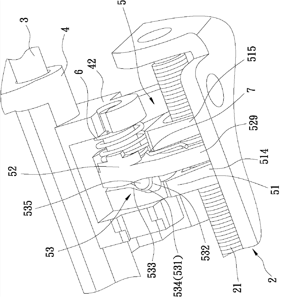
[0015] refer to image 3 , Figure 4 and Figure 5 A preferred embodiment of the transmission device of the optical equipment of the present invention includes a driving unit 2 , a guide member 3 , a frame body 4 , a jaw unit 5 , a first elastic member 6 and a second elastic member 7 .

[0016] The driving unit 2 includes a screw 21 disposed along the axis L, and a driving member 22 for driving the screw 21 to rotate around the axis L. In this embodiment, the driving member 22 can be a motor.

[0017] The guide 3 is arranged parallel to the screw 21 along the direction of the axis L. In this embodiment, the guide 3 is a guide rod.

[0018] The frame body 4 is used to carry optical components and includes a first pivot ear 41 and a second pivot ear 42 arran...


PUM


Abstract

The invention relates to a transmission device for optical equipment, which comprises a drive unit, a guide part, a frame sleeved on the guide part, a clamping jaw unit, a first elastic part and a second elastic part. The drive unit comprises a screw rod. The clamping jaw unit comprises a main clamping jaw and an assistant clamping jaw and is connected with the frame. The first elastic part is arranged on the frame and constantly keeps the main clamping jaw and the assistant clamping jaw to be close with each other so as to be tightly meshed with the screw rod. The second elastic part is arranged on the clamping jaw unit and constantly keeps the frame to push against the guide part. According to the transmission device, the screw rod is driven to rotate by the drive unit so as to drive the clamping jaw unit to lead the optical device on the frame to traverse the guide part; and the frame constantly pushes against the guide part, so that, the frame does not cause shake to result in deviation in optical imaging when being in movement.

Description

technical field [0001] The invention relates to a transmission device, in particular to a transmission device for optical equipment. Background technique [0002] Optical devices on the market, such as cameras, video cameras, etc., need to move the lens to an appropriate position through the transmission device to achieve the desired focal length when focusing. Therefore, the design accuracy of the transmission device will affect the imaging effect. [0003] refer to figure 1 and figure 2 , the known transmission device for optical equipment, as shown in the Chinese Taiwan Patent Publication No. 201035670 applied by the applicant, includes a screw 11, a guide 12, a frame 13 sleeved on the guide 12, and is arranged on the guide 12. The jaw unit 14 on the frame body 13 and the elastic member 15 . The jaw unit 14 includes a main jaw 141, an auxiliary jaw 142, and a cam module 143 respectively arranged between the main and auxiliary jaws 141, 142. The elastic member 15 const...

Claims


Application Information

Patent Timeline
IPC IPC(8): G02B7/04F16H25/20
Inventor 黄远升
Owner ASIA OPTICAL CO INC
Why Eureka
Try Eureka