A light-controlled smart lock

A smart lock and photoelectric sensor technology, applied in the field of visible light communication, can solve the problems of unable to drive or burn out the I/O port of the single-chip microcomputer, etc.

Active Publication Date: 2015-10-14
KUANG CHI INTELLIGENT PHOTONIC TECH
View PDF3 Cites 0 Cited by
  • Summary
  • Abstract
  • Description
  • Claims
  • Application Information

AI Technical Summary

Problems solved by technology

At present, the pull-up resistor is mainly used to improve the current driving capability, but if the pull-up resistor is too large, it may cause leakage current and burn the I / O port of the microcontroller, and at the same time, it cannot drive a large motor load to work normally.

Method used


Image

  • A light-controlled smart lock
  • A light-controlled smart lock
  • A light-controlled smart lock

Examples


Embodiment Construction

[0016] The technical solutions in the embodiments of the present invention will be clearly and completely described below in conjunction with the accompanying drawings in the embodiments of the present invention. Obviously, the described embodiments are only part of the embodiments of the present invention, not all of them. Based on the implementation manners in the present invention, all other implementation manners obtained by persons of ordinary skill in the art without creative efforts fall within the protection scope of the present invention.

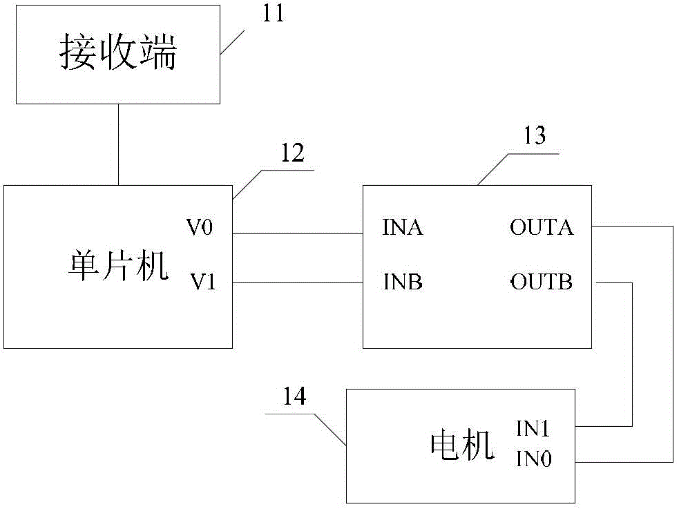
[0017] see figure 1 , is a schematic structural diagram of a light-controlled smart lock provided in Embodiment 1 of the present invention. The light-controlled smart lock includes:

[0018] The receiving end 11; the single-chip microcomputer 12 connected to the receiving end, the high-level output terminal V0 and the low-level output terminal V1 of the single-chip microcomputer 12 are respectively connected with the high-level inp...


PUM


Abstract

The invention discloses a light control smart lock, which comprises a visible light signal receiving terminal and a singlechip connected with the receiving terminal, wherein a high level output end and a low level output end of the singlechip are respectively connected with a high level input end and a low level input end of a drive circuit, and a high level output end and a low level output end of the drive circuit are respectively connected with a high level input end and a low level input end of a motor. As a result, the utilization efficiency of the battery at the controlled end of the access control system can be improved, and the normal operation of the motor for the gate lock can be ensured.

Description

technical field [0001] The invention relates to the technical field of visible light communication, in particular to a light-controlled intelligent lock. Background technique [0002] Visible light communication is a new, short-distance, high-speed wireless optical communication technology developed on the basis of LED technology. The basic principle of visible light communication is to use the characteristics of light-emitting diodes (LEDs) to switch faster than fluorescent lamps and incandescent lamps, and to communicate through high-frequency flickering of LED light sources. Light represents 1, and no light represents 0, sending out high-speed optical signals. The information is obtained through photoelectric conversion. Wireless optical communication technology can be used to make wireless optical encryption keys because its data is not easy to be interfered and captured, and optical communication equipment is simple to manufacture and should not be damaged or degaussed...

Claims


Application Information

Patent Timeline
Patent Type & Authority Patents(China)
IPC IPC(8): G07C9/00
Inventor 刘若鹏栾琳李春来李蔚
Owner KUANG CHI INTELLIGENT PHOTONIC TECH
Why Eureka
Try Eureka