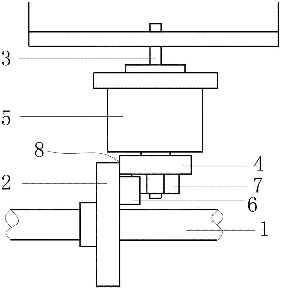
Advertising equipment capable of turning over on three sides
A technology of three-sided turning and advertising, which is applied in the direction of instruments, identification devices, etc., can solve the problems of increased motor load, content confusion, confusion, etc., and achieve the effect of reducing motor damage, reducing the number of motors, and reducing maintenance costs
- Summary
- Abstract
- Description
- Claims
- Application Information
AI Technical Summary
Problems solved by technology
Method used
Image
Examples
Embodiment 1
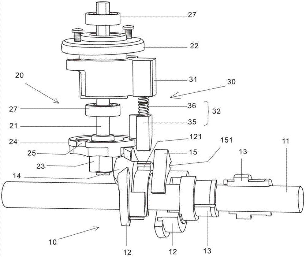
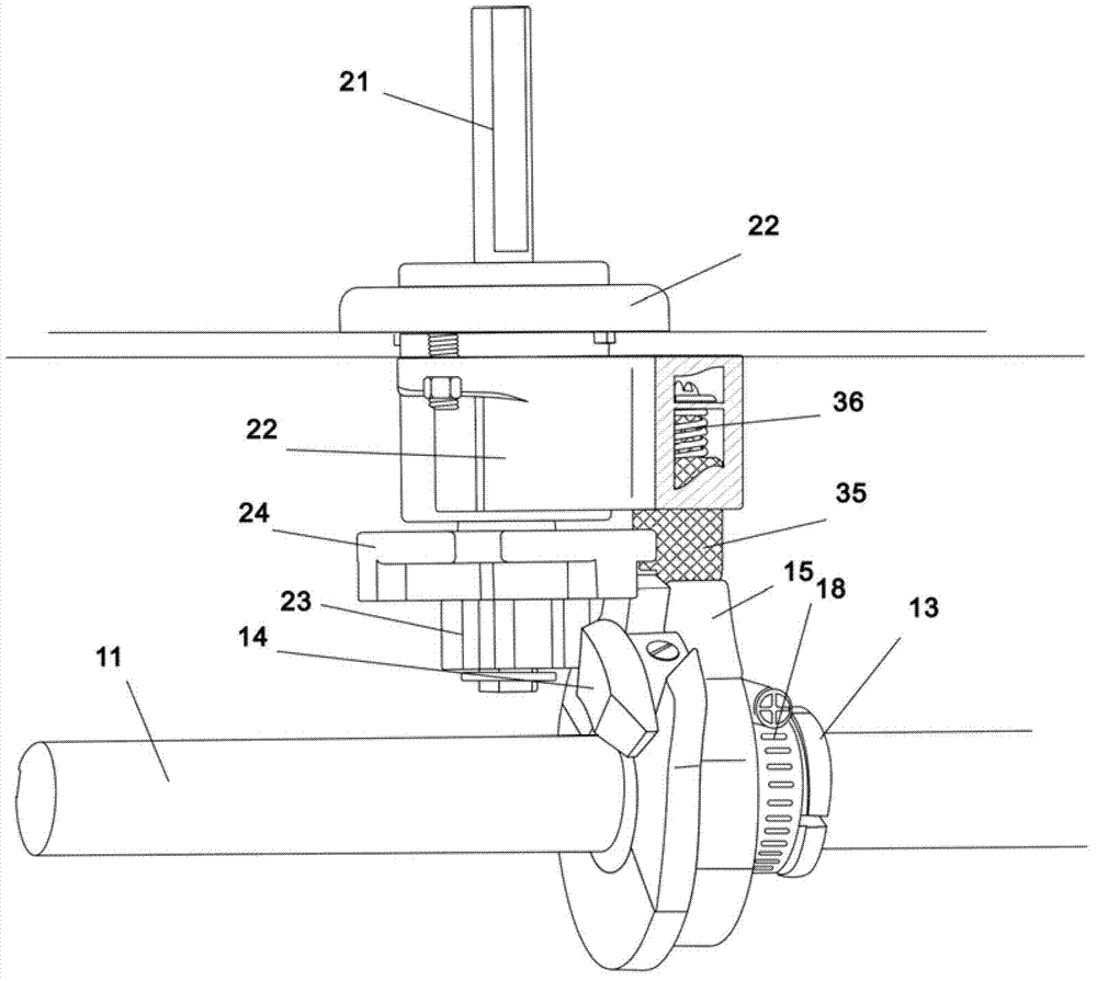
[0023] Such as figure 2 , image 3 As shown, the transmission mechanism of this three-sided advertising device includes a driving shaft assembly 10 and a driven shaft assembly 20, wherein the driving shaft assembly 10 includes a driving shaft 11 connected to a motor and a driving wheel 12 integrally connected to the driving shaft, in order to prevent The driving wheel 12 is offset, and a fastener is used. The fastener is formed by a symmetrical two-lobed driving wheel inner sleeve 13 set on the driving shaft 11 and fixed with a hoop 18; The inner side of the driving wheel 12, that is, the side close to the driven shaft assembly 20; correspondingly, the driven shaft assembly 20 includes a driven shaft 21 perpendicular to the driving shaft 11 for fixedly connecting the triangular prism and a supporting shaft for supporting the driven shaft 21 The bearing housing 22 and the bearing 27 are connected between the driven shaft 21 and the bearing housing 22. The lower end of the dri...
Embodiment 2
[0032] Such as Figure 4 , Figure 5 As shown, the transmission mechanism of this three-sided advertising device provided by the present invention is the same as the existing ones, including a driving shaft assembly 10 and a driven shaft assembly 20, wherein the driving shaft assembly 10 includes a driving shaft 11 connected to a motor and an integrally connected For the driving wheel 12 of the driving shaft, in order to prevent the driving wheel 12 from shifting, a fastener 13 (that is, the inner kit of the driving wheel in the embodiment) is used. The driving wheel 12 is provided with a driving tooth 14, which is located inside the driving wheel 12. That is, it is close to the side of the driven shaft assembly 20; correspondingly, the driven shaft assembly 20 includes a driven shaft 21 perpendicular to the driving shaft 11 for fixedly connecting the triangular prism and a bearing seat 22 for supporting the driven shaft 21, The end of the driven shaft 21 is fixedly connected...
Embodiment 3
[0039] Such as Figure 6 As shown, the difference from the above embodiments is that the driving gear on the driving wheel 12 can be replaced by a bevel gear 16, and correspondingly, the meshing part of the driven wheel 23 is a bevel gear 26, and the driving wheel 12 can also be used to drive the driven wheel. 23 transmissions, and can accurately control its angle of rotation, according to the working characteristics of this three-sided turning, turn 120 degrees when turning over at every turn, so the number of teeth of bevel gear 16 is determined by bevel gear 26, with each rotation 120 degrees as the limit.
[0040] The positioning mechanism used in this embodiment is similar to that of Embodiment 1, and its motion principle is the same as that of the above embodiment, so it will not be repeated here.
PUM
 Abstract
Description
Claims
Application Information
 - R&D
- Intellectual Property
- Life Sciences
- Materials
- Tech Scout
- Unparalleled Data Quality
- Higher Quality Content
- 60% Fewer Hallucinations
Browse by: Latest US Patents, China's latest patents, Technical Efficacy Thesaurus, Application Domain, Technology Topic, Popular Technical Reports.
© 2025 PatSnap. All rights reserved.Legal|Privacy policy|Modern Slavery Act Transparency Statement|Sitemap|About US| Contact US: help@patsnap.com


