Automatic assembling machine for electric brush of micro-motor end cover

An automatic assembly machine and brush technology, applied in the direction of electric components, electromechanical devices, manufacturing motor generators, etc., can solve the problems of high cost, difficult end caps, accurate positioning, etc., to ensure accuracy and stability, pressure resistance And strong impact resistance, the effect of reducing production costs

Active Publication Date: 2012-11-07
GUANGDONG CHAOLI MOTOR CO LTD
View PDF3 Cites 40 Cited by
  • Summary
  • Abstract
  • Description
  • Claims
  • Application Information

AI Technical Summary

Problems solved by technology

[0003] Restricted by the structure of the end cap and the brush, at present, the assembly of the brush on the end cap of the micro-motor is still a manual or semi-automatic operation. In the case of semi-automatic operation, the end cap of the micro-motor The brush assembly is divided into several sections, namely the plugging brush section, the pressing brush section, the first glue dispensing section, the second glue dispensing section, etc., and adopts flow operation, although some pressing devices and dispensing devices are used. , but the degree of manual intervention is still very large, and a worker is required to perform corresponding operations on each section
At present, the assembly method of this micro-motor end cover has the following disa

Method used


Image

  • Automatic assembling machine for electric brush of micro-motor end cover
  • Automatic assembling machine for electric brush of micro-motor end cover
  • Automatic assembling machine for electric brush of micro-motor end cover

Examples


Embodiment Construction

[0038] Further description will be given below in conjunction with the accompanying drawings and preferred embodiments of the present invention.

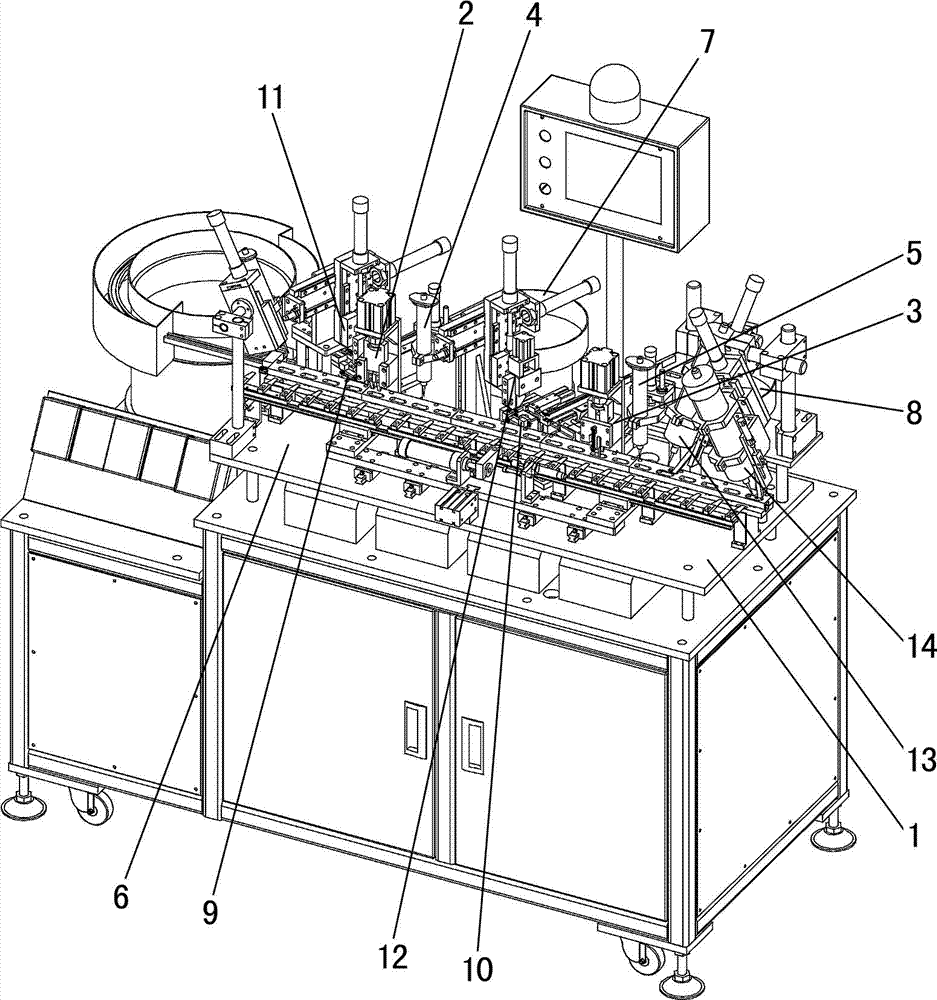
[0039] Such as figure 1 As shown, the brush automatic assembly machine for the micro-motor end cover includes frame 1, left brush pressing mechanism 2, right brush pressing mechanism 3, left brush first dispensing mechanism 4, right brush First dispensing mechanism 5, end cover conveying mechanism 6, left brush queuing mechanism 7, right brush queuing mechanism 8, left brush conveying and positioning mechanism 9, right brush conveying and positioning mechanism 10, left brush grasping and plugging Mechanism 11, right electric brush grasping and plugging mechanism 12, left electric brush second glue dispensing mechanism 13 and right electric brush second glue dispensing mechanism 14.

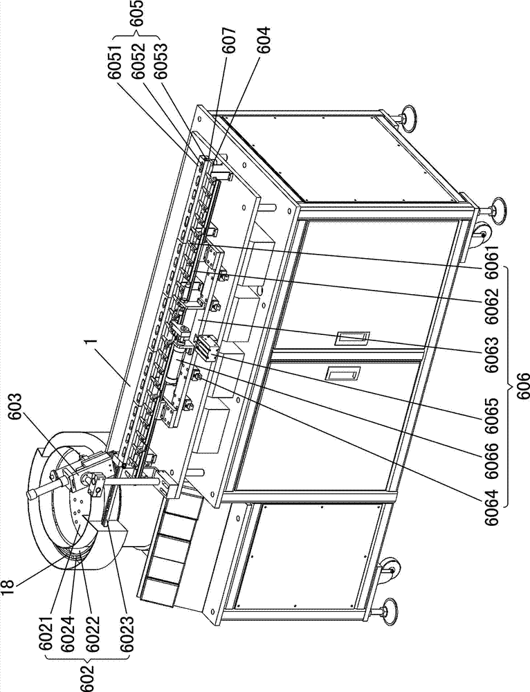
[0040] Such as figure 2 As shown, the above-mentioned end cap conveying mechanism 6 includes an end cap unscrambling device 602, an end cap distribu...


PUM


Abstract

The invention relates to an automatic assembling machine for electric brushes of a micro-motor end cover. The automatic assembling machine comprises a rack, a left electric brush pressing mechanism, a right electric brush pressing mechanism, a left electric brush first glue dispensing mechanism, a right electric brush first glue dispensing mechanism, an end cover conveying mechanism, a left electric brush queuing mechanism, a right electric brush queuing mechanism, a left electric brush conveying and positioning mechanism, a right electric brush conveying and positioning mechanism, a left electric brush grabbing and inserting mechanism and a right electric brush grabbing and inserting mechanism. Starting from positioning and orientation of end covers, the end cover is tidily arranged in a fixing direction through an end cover tidying device, then the end covers are conveyed through end cover conveying rails in combination with an end cover poking mechanism to ensure that the end covers are accurately conveyed to a designated position and the fixing direction is kept unchanged, and finally subsequent processes such as electric brush insertion, pressing and glue dispensing are conducted. The problems that the end covers are difficult to position and cannot be oriented in the conveying and operating process and the operating accuracy and stability cannot be guaranteed are solved, the full-automatic assembling of the end cover electric brushes of a micro-motor is realized, the production efficiency is improved and the production cost is reduced.

Description

technical field [0001] The invention relates to an assembly device of a micro-motor, in particular to an automatic brush assembly machine for the end cover of a micro-motor. Background technique [0002] The end cover of the micro-motor includes a cover body, the cover body has two parallel straight sides, and two protrusions and two brush slots (left brush slot and right brush slot) are symmetrically arranged on the cover body. The brush generally includes a plug arm, a brush arm and a carbon brush block. One end of the brush arm is connected to one end of the plug arm, and the brush arm is perpendicular to the plug arm, and the carbon brush block is arranged at the other end of the brush arm. [0003] Restricted by the structure of the end cap and the brush, at present, the assembly of the brush on the end cap of the micro-motor is still a manual or semi-automatic operation. In the case of semi-automatic operation, the end cap of the micro-motor The brush assembly is divi...

Claims


Application Information

Patent Timeline
IPC IPC(8): H02K15/00H02K15/14
Inventor 陈祉浩张彦志杨壮凌
Owner GUANGDONG CHAOLI MOTOR CO LTD
Why Eureka
Try Eureka