Proportional valve, assembling method of proportional valve

A technology of proportional valves and check valves, applied in the field of proportional valves, can solve problems such as proportional valve failures, achieve the effects of short hydraulic distance, simple and reliable assembly, and minimize the risk of assembly errors

Active Publication Date: 2015-05-06
SCHAEFFLER TECH AG & CO KG
View PDF7 Cites 0 Cited by
  • Summary
  • Abstract
  • Description
  • Claims
  • Application Information

AI Technical Summary

Problems solved by technology

Such a collision can lead to failure of the proportional valve

Method used


Image

  • Proportional valve, assembling method of proportional valve
  • Proportional valve, assembling method of proportional valve
  • Proportional valve, assembling method of proportional valve

Examples


Embodiment Construction

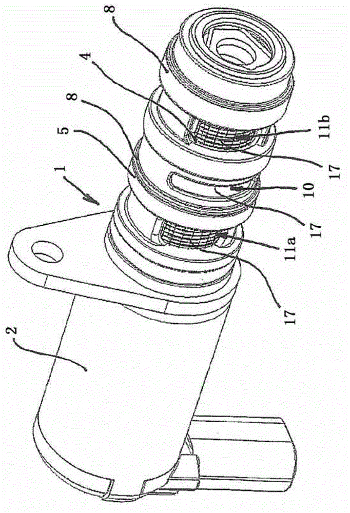
[0017] The proportional valve 1 according to the present invention is provided with a camshaft adjuster for an internal combustion engine. Here, the function of the camshaft driven by the camshaft adjuster in the internal combustion engine is that the camshaft overcomes the force of the valve spring installed on each gas exchange valve, opens the exchange for exhausting the burned gas and sucking fresh gas. Gas valve. The rigid valve timing for the gas exchange valve is for the maximum achievable medium pressure or maximum torque, its position in the usable speed range and the power that can be achieved at the rated speed. A compromise in terms of design. The camshaft adjuster can realize the optimal adaptation of the valve timing of the gas exchange valve corresponding to the respective operating state.

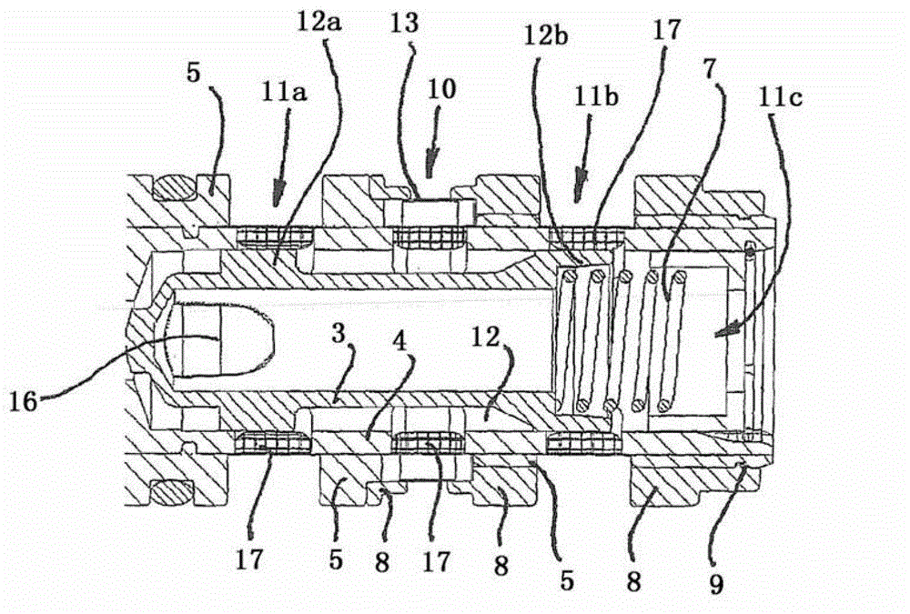
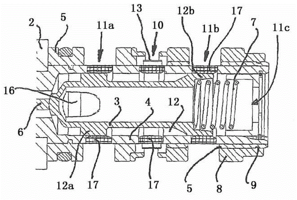
[0018] Proportional valve 1 is based on figure 1 There is an electromagnetic control part 2, the control piston 6 and the valve piston 3 ( figure 2 , 3 , 4) Co-act in propor...


PUM


Abstract

A proportional valve (1), including a piston guide sleeve (4) and a valve piston (3) that can be moved in the piston guide sleeve (4), and further including a check valve (13) arranged in a pressure medium inlet (10) to the proportional valve (1). According to the invention a proportional valve (1) is provided, in which the adaption of the check valve (13) to the proportional valve (1) is improved with respect to the prior art. This is achieved in that the check valve (13) is arranged in an annular gap (14) surrounding the piston guide sleeve (4) in a region of the pressure medium inlet (10).

Description

Technical field [0001] The present invention relates to a proportional valve with a piston guide sleeve and a valve piston movable in the piston guide sleeve and a check valve arranged in the pressure medium inlet leading to the proportional valve and for this type Assembly method of proportional valve. Background technique [0002] DE 10 2005 060 111 A1 discloses a proportional valve of this type. The proportional valve is designed for camshaft adjusters for internal combustion engines and is integrated into the central bolt for attaching the camshaft adjusters to the camshaft. In this case, the proportional valve has a non-return valve which is constructed in the shape of a spring-loaded disk and is arranged laterally next to the proportional valve on the outer periphery of the central screw in the annular pressure medium inlet. During the assembly, attention must be paid to installing the non-return valve, which is arranged separately from the proportional valve, and in addi...

Claims


Application Information

Patent Timeline
Patent Type & Authority Patents(China)
IPC IPC(8): F01L1/344F16K15/14
CPCF01L1/344Y10T29/49405Y10T137/7837F16K15/14F01L1/24F01L1/26F01L9/10F01L13/00F16H7/08
Inventor 延斯·霍佩斯特凡·科尼亚斯王毅
Owner SCHAEFFLER TECH AG & CO KG
Why Eureka
Try Eureka