Steel wire rope binding machine

A technology of binding device and steel wire rope, which is applied to the binding of ends, textiles, papermaking, textile cables, etc., can solve the problems of time-consuming, small binding force, easy relaxation, etc., and achieves simple and compact structure, large binding force, and strong practicability. Effect

Inactive Publication Date: 2012-11-14
JULI SLING
View PDF6 Cites 5 Cited by
  • Summary
  • Abstract
  • Description
  • Claims
  • Application Information

AI Technical Summary

Problems solved by technology

[0002] The binding of the traditional steel wire rope end or rope body is purely manual operation, which has the disadvantages of time-consuming, laborious, small binding force and easy slack.
At present, there are two commonly used methods of manual winding to achieve bundling: 1. Take the bundling rope ball and wrap it back and forth on the rope body and pre-tighten it by hand. Tight, but for the rope body with a long binding distance, manual pretensioning is not tight, and it is labor-intensive and time-consuming
2. For the wire rope end or rope body that requires a large binding force, use a wooden board with holes to pass the bundled sub-ropes through the board continuously, and coil the remaining sub-ropes into a ball. The operator holds the rope ball and makes the board with holes surround the wire rope. Winding, the rope must be hand-transmitted for a circle every time it is wound, and it is also more laborious and time-consuming for the rope with a longer binding distance

Method used


Image

  • Steel wire rope binding machine
  • Steel wire rope binding machine
  • Steel wire rope binding machine

Examples


Embodiment Construction

[0020] The preferred embodiments of the present invention will be described below in conjunction with the accompanying drawings. It should be understood that the preferred embodiments described here are only used to illustrate and explain the present invention, and are not intended to limit the present invention.

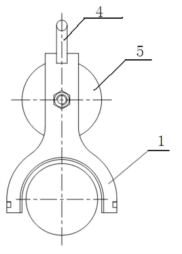
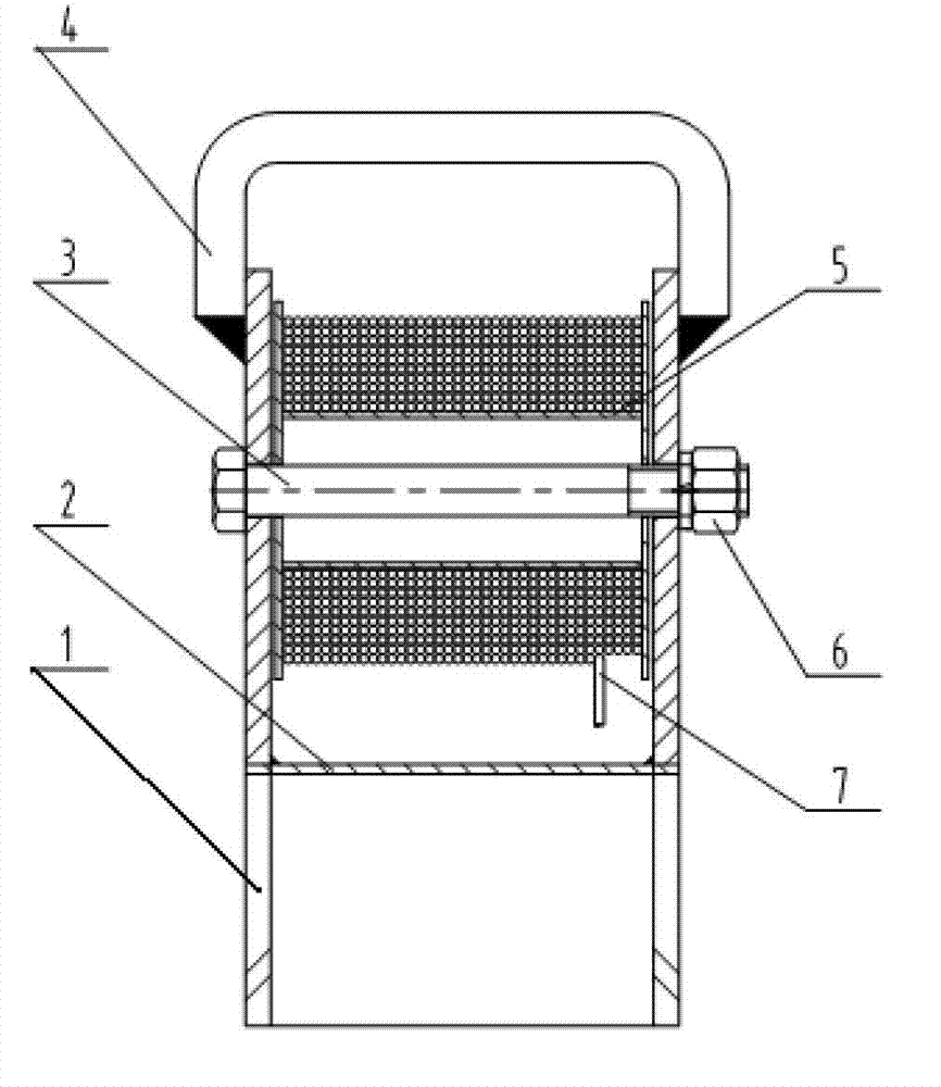
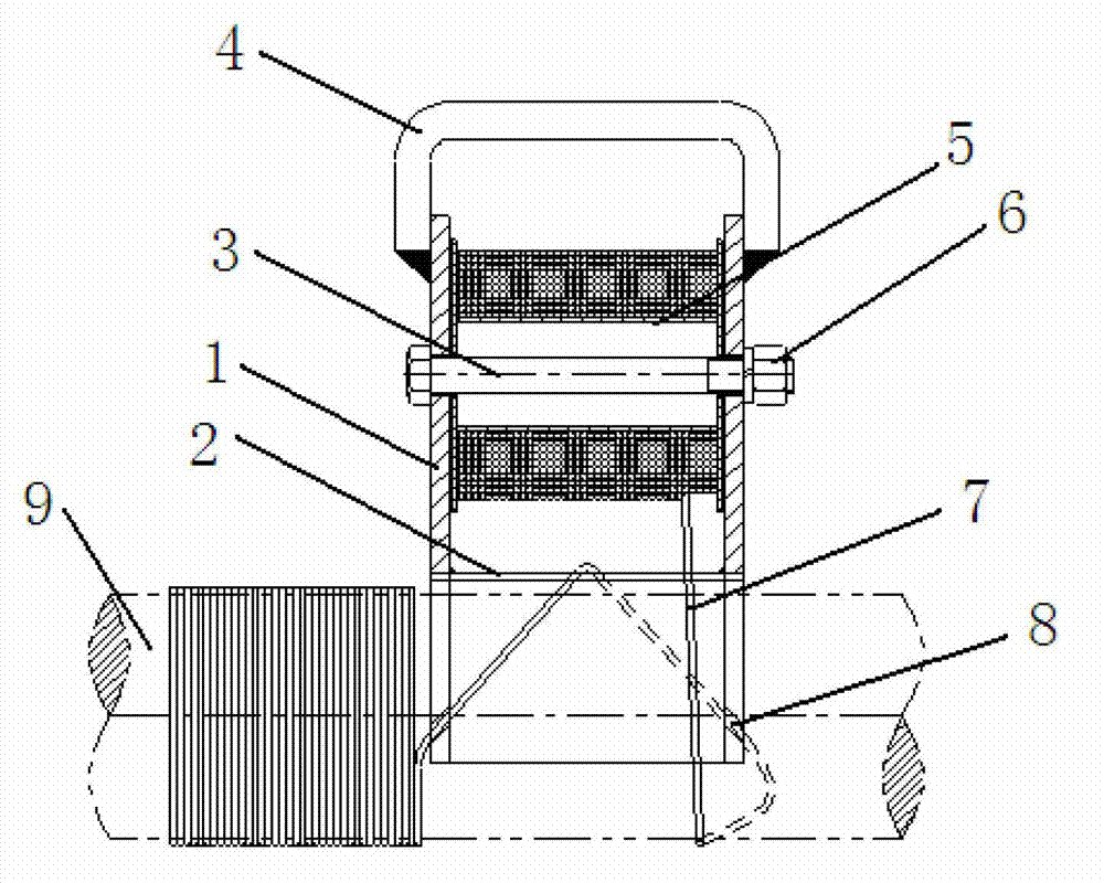
[0021] Such as figure 1 , figure 2 As shown, the wire rope binding device includes an I-shaped wheel bracket and an I-shaped wheel 5. The I-shaped wheel bracket includes a side guide plate 1, an arc plate 2, a pin shaft 3, a handle 4, and a lock nut 6. The two side guide plates 1 is connected between the arc plate 2 and the pin shaft 3 that runs through the side guide plate, and a guide groove 8 is respectively opened on the two side guide plates 1, and the angle between the guide groove 3 and the side guide plate 1 is 40-75 degrees; The guide grooves of the block side guide plate 1 are on different sides, and the winding rope 7 is exported by the guide groove 8 o...


PUM


Abstract

The invention provides a steel wire rope binding machine. The steel wire rope binding machine comprises an I-shaped wheel bracket and an I-shaped wheel, wherein the I-shaped wheel bracket comprises side guide plates, an arc plate, a pin shaft, a handle and a locking nut; the arc plate and the pin roll getting out of the side guide plates are connected between the two side guide plates; the I-shaped wheel rotating surrounding the pin roll is sleeved outside the pin roll; a winding rope is wound on the outer circumference of the I-shaped wheel; the pin shaft is arranged above the arc plate; the end part of the pin shaft is fixed by the locking nut; the arc plate is fixed on the lower ends of the side guide plates; and the handle is connected outside the upper ends of the two side guide plates. The steel wire rope binding machine is suitable for binding steel wire ropes, and also suitable for binding diameter products and objects, and has the characteristics of big binding force and high working efficiency.

Description

technical field [0001] The invention belongs to the steel wire rope sling manufacturing technology, in particular to the binding applied to the rope body and the end of the steel wire rope. Background technique [0002] The binding of the traditional steel wire rope end or rope body is purely manual, which has the disadvantages of time-consuming, laborious, small binding force, and easy slack. At present, there are two commonly used methods of manual winding to achieve bundling: 1. Take the bundling rope ball and wrap it back and forth on the rope body and pre-tighten it by hand. It is tight, but for the rope body with a long binding distance, the manual pretension is not tight, and it is labor-intensive and time-consuming. 2. For the wire rope end or rope body that requires a large binding force, use a wooden board with holes to pass the bundled sub-ropes through the board continuously, and coil the remaining sub-ropes into a ball. The operator holds the rope ball and make...

Claims


Application Information

Patent Timeline
Patent Type & Authority Applications(China)
IPC IPC(8): D07B9/00
Inventor 杨建国张立新刘晗孙会安王文生
Owner JULI SLING
Why Eureka
Try Eureka