Valve module

A technology of valve components and valve stems, which is applied in the direction of balance valves, valve devices, valve details, etc., can solve the problems of increasing the complexity of installation and replacing parts, and achieves the effects of low cost, simple replacement and multi-flexibility

Active Publication Date: 2012-11-14
FISHER JEON GAS EQUIP CHENGDU
View PDF10 Cites 7 Cited by
  • Summary
  • Abstract
  • Description
  • Claims
  • Application Information

AI Technical Summary

Problems solved by technology

[0006] However, if Figure 2a , 2b The problem with the known pilot valves shown is that the port pads 031, 031' need to be coupled to the diaphragms 034, 034', thus requiring additional elements 035, 036 etc. and adding to the complexity of installation, replacement parts Spend

Method used


Image

  • Valve module
  • Valve module
  • Valve module

Examples


Embodiment Construction

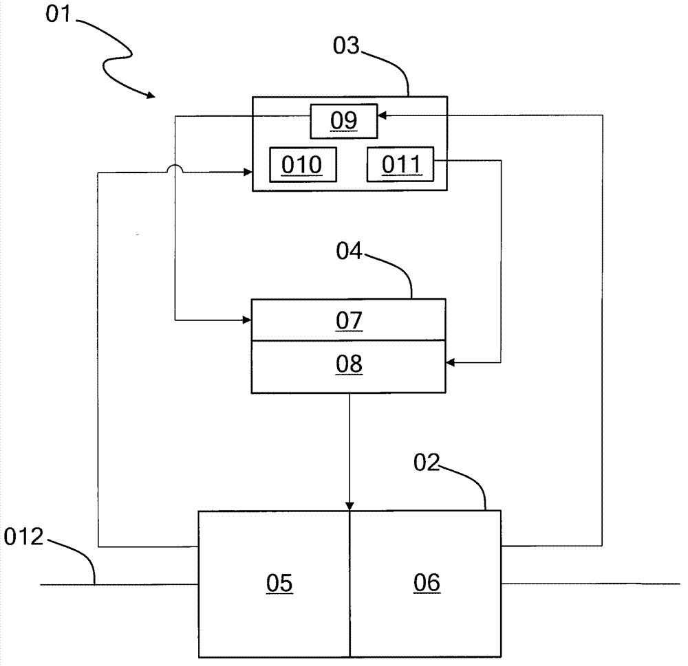
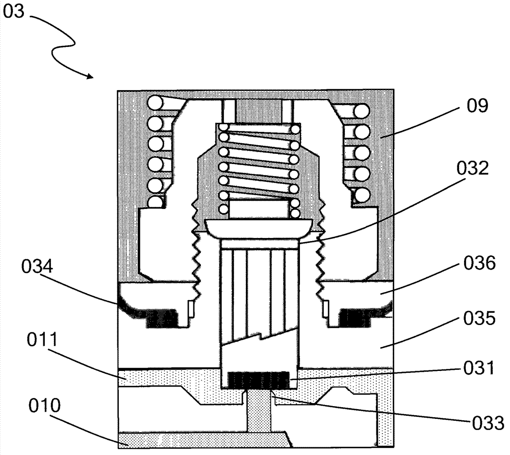
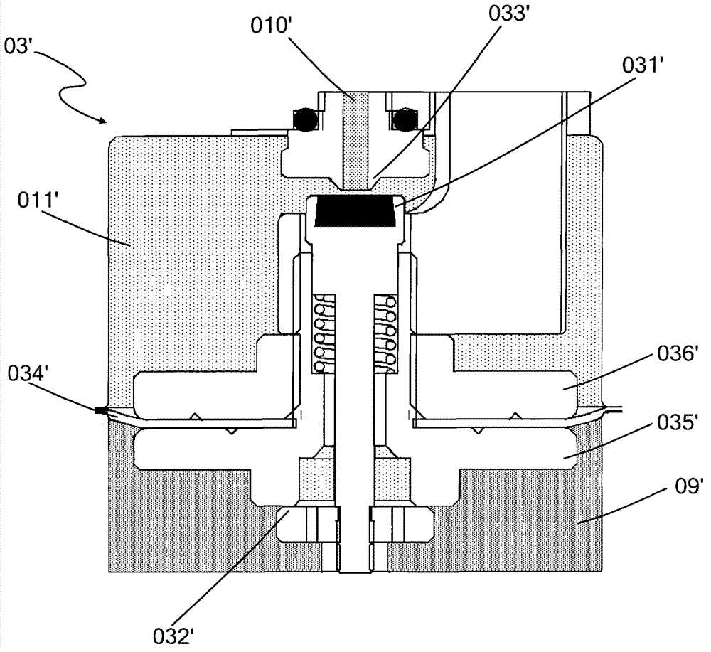
[0039] In the following detailed description of the preferred embodiment, reference is made to the accompanying drawings which form a part hereof. The accompanying drawings show, by way of example, specific embodiments in which the invention can be practiced. The illustrated embodiments are not intended to be exhaustive of all embodiments in accordance with the invention. It is to be understood that other embodiments may be utilized and structural or logical changes may be made without departing from the scope of the present invention. Accordingly, the following detailed description is not limiting, and the scope of the invention is defined by the appended claims.

[0040] In the following detailed description, reference is made to the accompanying drawings. The accompanying drawings, which constitute a part of this invention, show by way of example specific embodiments in which the invention can be practiced. In this regard, directional terms such as "left", "right", "top"...


PUM


Abstract

The invention relates to a valve module. The valve module comprises a valve body, a blocking device, a valve rod and a diaphragm, wherein the valve body comprises a first pressure cavity and a second pressure cavity. The pressure of the first pressure cavity is lower than that of the second pressure cavity, and the pressure of the second pressure cavity is released to the first pressure cavity corresponding to pressure variation of the first pressure cavity. The blocking device is arranged between the first pressure cavity and the second pressure cavity, the valve rod is arranged in the valve body, one end of the valve rod is movably contacted with the blocking device, and the diaphragm is connected to the valve rod and is close to or is arranged on the first pressure cavity. When the pressure of the first pressure cavity varies, the diaphragm responds to pressure variation of the first pressure cavity to drive the valve rod to move.

Description

technical field [0001] The present invention relates to a pressure regulating device, and more particularly to a quick-release assembly and a valve assembly comprising the pressure regulating device. Background technique [0002] Command valve is also called pilot, pilot valve (pilot valve). A pilot valve is usually used to control the operation of a pressure regulating valve (pressure regulator). [0003] figure 1 A typical pressure regulator valve assembly 01 is shown, including main valve 02 , pilot valve 03 , and actuator 04 . Specifically, the main valve 02 is connected to the main fluid pipeline 012, and the valve body of the main valve 02 includes an inlet cavity 05 and an outlet cavity 06, wherein the inlet cavity 05 is coupled to a fluid source (for example, a gas supply station) through the pipeline 012, and the outlet cavity The oral cavity 06 is coupled to a fluid recipient (eg a gas consumer) via a line 012 . As is generally known, the connection and disconn...

Claims


Application Information

Patent Timeline
Patent Type & Authority Applications(China)
IPC IPC(8): F16K31/126
CPCF16K17/10G05D16/16Y10T137/7762F16K31/126
Inventor 王乐
Owner FISHER JEON GAS EQUIP CHENGDU
Why Eureka
Try Eureka