
Display panel of stereoscopic image display

A display panel and stereoscopic image technology, applied in stereoscopic systems, instruments, image communications, etc., can solve problems such as poor contrast and image quality, reduced brightness of the display panel, and impact

Active Publication Date: 2012-11-14
SHENZHEN CHINA STAR OPTOELECTRONICS TECH CO LTD
View PDF3 Cites 9 Cited by
  • Summary
  • Abstract
  • Description
  • Claims
  • Application Information

AI Technical Summary

Problems solved by technology

[0009] Due to the problem of video crosstalk, 3D displays have a low viewing angle, so they have a certain ability to prevent information leakage, but there is still room for improvement
However, this method will reduce the overall brightness of the display panel, which will adversely affect the contrast and image quality.

Method used


Image

  • Display panel of stereoscopic image display
  • Display panel of stereoscopic image display
  • Display panel of stereoscopic image display

Examples


Embodiment Construction

[0033] The following descriptions of the various embodiments refer to the accompanying drawings to illustrate specific embodiments in which the present invention can be practiced. The directional terms mentioned in the present invention, such as "up", "down", "front", "back", "left", "right", "top", "bottom", "horizontal", "vertical", etc. , are for orientation only with reference to the attached drawings. Therefore, the directional terms used are used to illustrate and understand the present invention, but not to limit the present invention.

[0034] Figure 7 A schematic diagram showing the display panel of the stereoscopic image display of the present invention, Figure 8 A schematic diagram showing polarized glasses used in conjunction with the stereoscopic image display in the present invention. Such as Figure 7 As shown, the display panel for stereoscopic image display of the present invention includes a backlight plate 21 , a polarizer 22 , a thin film transistor a...


PUM


Abstract

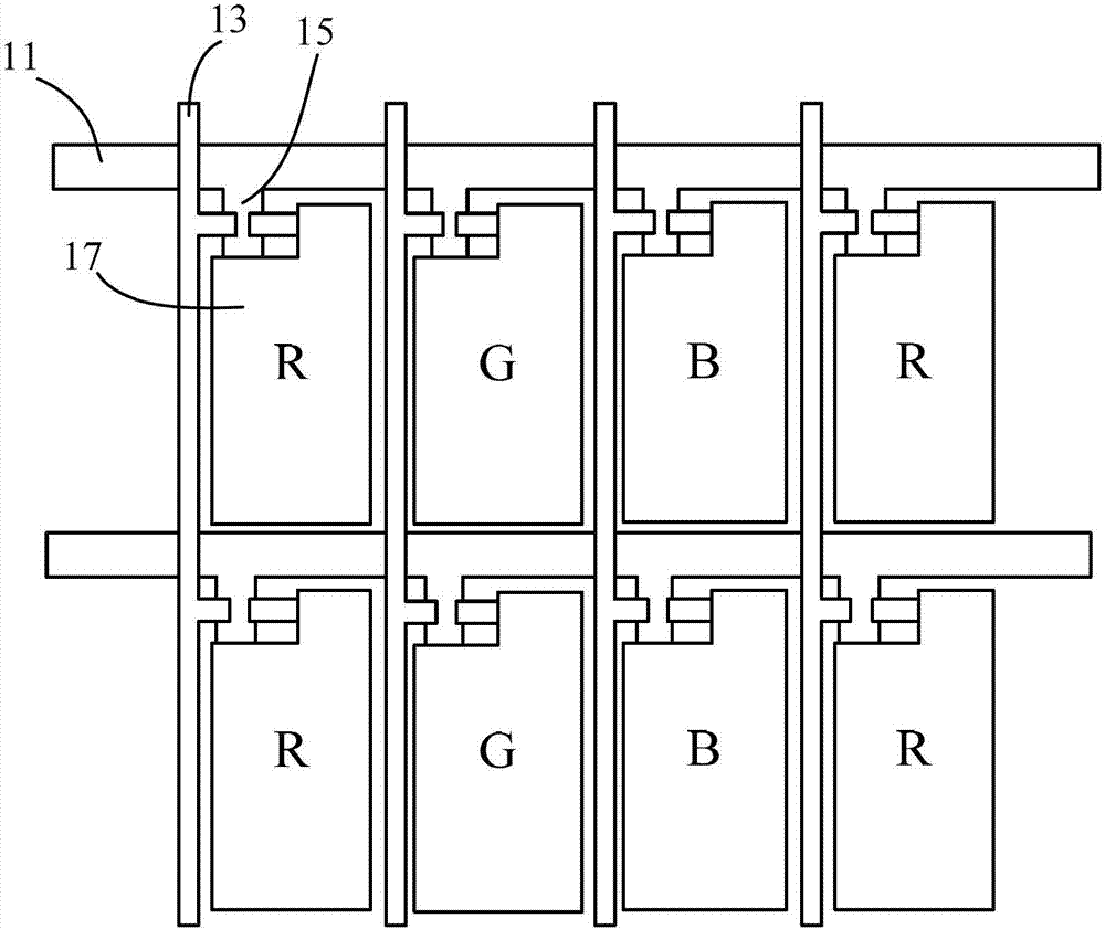
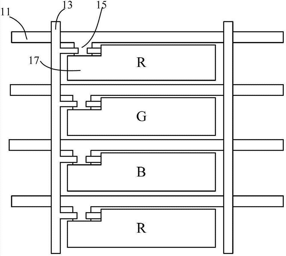
The invention provides a display panel of a stereoscopic image display. The display panel comprises a plurality of pixel regions, red, blue and green sub-pixel regions in each pixel region are arranged in parallel along the vertical direction, the blue sub-pixel region in each pixel region is in the middle of the pixel region, and the red and green sub-pixel regions in each pixel region are at the upper side and the lower side of the pixel region. With the adoption of the arrangement, the viewing angle of the display panel of the stereoscopic image display can be further reduced, so that the confidentiality of displayed image information can be promoted to prevent information leakage.

Description

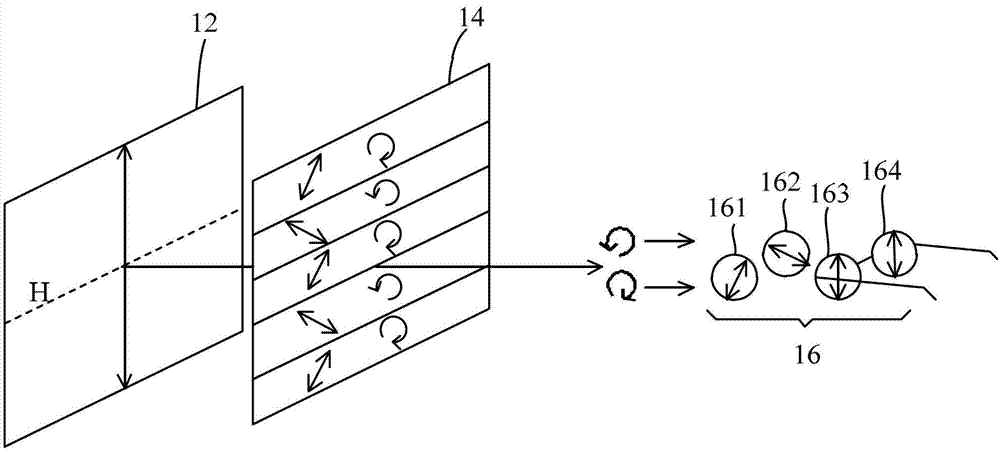
technical field [0001] The invention relates to a stereoscopic image display technology, in particular to a display panel of a stereoscopic image display. Background technique [0002] With the vigorous development of liquid crystal displays, stereoscopic displays (3D displays) capable of presenting stereoscopic images have gradually entered the market. Because the 3D display device can present the distance relationship of objects, which is consistent with the human visual form, it is expected to become the development direction of the next generation display. [0003] figure 1 A schematic diagram showing the working principle of an existing stereoscopic display. Existing 3D displays mainly adopt pattern retarder technology and cooperate with polarized glasses to present 3D images. Such as figure 1 As shown, a linear polarizer 12 is arranged on the side of the TFT array substrate (not shown) of the display, and a λ / 4 array waveplate 14 is arranged on the side of the colo...

Claims


Application Information

Patent Timeline
IPC IPC(8): G02F1/1335G02B27/26H04N13/04G02B30/25
CPCH04N13/04G02F1/133514G02F1/1335G02F2201/52G02B30/25H04N13/337
Inventor 廖巧生萧嘉强陈峙彣
Owner SHENZHEN CHINA STAR OPTOELECTRONICS TECH CO LTD
Learn More