Supercharge Your Innovation With Domain-Expert AI Agents!

Optical fiber repeater system

An optical fiber repeater and optical fiber technology, applied in the field of repeater systems, can solve the problems of lack of full redundant hot backup and core module cross hot backup, radio frequency communication base station coverage not reaching ideal coverage, low reliability, etc. , to achieve the effect of meeting the requirements of rapid maintenance without interrupting the signal, facilitating identification and maintenance, and high reliability

Inactive Publication Date: 2015-04-08
深圳市虹远通信有限责任公司
View PDF10 Cites 0 Cited by
  • Summary
  • Abstract
  • Description
  • Claims
  • Application Information

AI Technical Summary

Problems solved by technology

[0002] Optical fiber repeaters can effectively solve the problem that the coverage of radio frequency communication base stations cannot achieve ideal coverage due to factors such as building shelter, ground absorption, and space loss. However, traditional optical fiber repeaters usually include fiber optic near-end machines. It is composed of a duplexer, a near-end optical integrated module and a power module. The optical fiber remote machine is composed of a duplexer, a remote optical integrated module, a radio frequency integrated module and a power module. The middle of the optical fiber near-end machine and the optical fiber remote machine It is often connected by single-mode transmission optical fiber, that is, mostly adopts master-slave backup for the optical fiber of the transmission link, or can only achieve parallel backup of some radio frequency modules, and does not have full redundant hot backup of the entire system and cross hot backup of core modules other functions, low reliability

Method used


Image

  • Optical fiber repeater system
  • Optical fiber repeater system

Examples


Embodiment 1

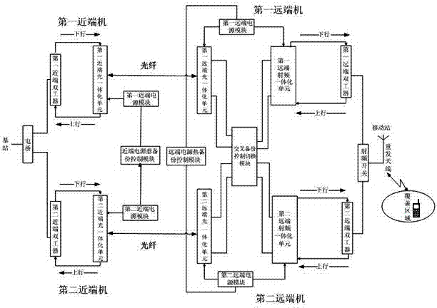
[0063] Such as figure 1 As shown, this example provides an optical fiber repeater system, including:

[0064] The first near-end machine is connected to an external base station through a bridge;

[0065] A first near-end power supply module, configured to supply power to the first near-end machine;

[0066] The first remote machine is connected to the first near-end machine through an optical fiber;

[0067] The second near-end machine is connected to an external base station through a bridge;

[0068] A second near-end power supply module, configured to supply power to the second near-end machine;

[0069] The second remote machine is connected to the second near-end machine through an optical fiber;

[0070] a radio frequency switch, respectively receiving the outputs of the first remote machine and the second remote machine;

[0071] A retransmission antenna, used to transmit the signal output by the radio frequency switch;

[0072] A near-end power supply hot backup...

Embodiment 2

[0085] Different from Embodiment 1, the first near-end machine described in this example includes:

[0086] The first near-end duplexer is connected to an external base station through a bridge;

[0087] The first near-end optical integration unit is connected to the first remote machine through an optical fiber, and forms an uplink and downlink link with the first near-end duplexer.

[0088] Wherein, the first near-end duplexer isolates the downlink transmission signal of the first near-end unit from the uplink reception signal to ensure that both reception and transmission can work normally at the same time; the first near-end optical integration The optical unit includes a first near-end optical disc subunit and a first near-end monitoring disc subunit; the first near-end optical disc subunit is used to convert radio frequency signals into optical signals; the first near-end monitoring disc subunit is used to query and set the first A near-end machine monitors parameters a...

Embodiment 3

[0091] Different from Embodiment 2, the second near-end machine described in this example includes:

[0092] The second near-end duplexer is connected to an external base station through a bridge;

[0093] The second near-end optical integration unit is connected to the second remote machine through an optical fiber, and forms an uplink and downlink link with the second near-end duplexer.

[0094] Wherein, the second near-end duplexer isolates the downlink transmission signal of the second near-end unit from the uplink reception signal to ensure that both reception and transmission can work normally at the same time; the second near-end optical integration The optical unit includes a second near-end optical disc subunit and a second near-end monitoring disc subunit; the second near-end optical disc subunit is used to convert radio frequency signals into optical signals; the second near-end monitoring disc subunit is used to query and set the first The second near-end machine ...


PUM


Abstract

The invention provides an optical fiber repeater system which comprises a first near-end machine, a first near-end power module, a first far-end machine, a second near-end machine, a second near-end power module, a second far-end machine, a radio frequency switch, a retransmission antenna, a near-end power heat backup control module, a cross backup control switching module, a first far-end power module, a second far-end power module and a far-end power heat backup control module for respectively controlling the first far-end power module and the second far-end power module, wherein the cross backup control switching module respectively detects and judges whether the first far-end machine and the second far-end machine fail; when any one of the far-end machine fails, a signal is switched to the other far-end machine; when optical integration units or radio frequency integration units in the two far-end machines fail, the signal is switched to the corresponding units which do not fail; and therefore, cross backup of key units is realized.

Description

technical field [0001] The invention relates to a repeater system, in particular to an optical fiber repeater system. Background technique [0002] Optical fiber repeaters can effectively solve the problem that the coverage of radio frequency communication base stations cannot achieve ideal coverage due to factors such as building shelter, ground absorption, and space loss. However, traditional optical fiber repeaters usually include fiber optic near-end machines. It is composed of a duplexer, a near-end optical integrated module and a power module. The optical fiber remote machine is composed of a duplexer, a remote optical integrated module, a radio frequency integrated module and a power module. The middle of the optical fiber near-end machine and the optical fiber remote machine It is often connected by single-mode transmission optical fiber, that is, mostly adopts master-slave backup for the optical fiber of the transmission link, or can only achieve parallel backup of ...

Claims


Application Information

Patent Timeline
Patent Type & Authority Patents(China)
IPC IPC(8): H04B10/291H04B10/038H04B10/29
Inventor 马印斌廖德祥王昌文林凯
Owner 深圳市虹远通信有限责任公司
Features
  • R&D
  • Intellectual Property
  • Life Sciences
  • Materials
  • Tech Scout
  • Unparalleled Data Quality
  • Higher Quality Content
  • 60% Fewer Hallucinations
Learn More