Turbomachine comprising a vertical shaft

一种涡轮机组、涡轮机的技术,应用在涡轮/推进装置的润滑、机械设备、发动机制造等方向,能够解决降低效力、增加涡轮机组重量、增加重量等问题,达到提高效率、节省重量、空间节省的效果

Active Publication Date: 2015-02-18
TURBOMECA SA
View PDF6 Cites 0 Cited by
  • Summary
  • Abstract
  • Description
  • Claims
  • Application Information

AI Technical Summary

Problems solved by technology

[0004] The second flaw is related to the use of multiple bearings, which increases the weight of the turbomachine and reduces its effectiveness
This cooling system is complicated to install and maintain, and will increase the manufacturing and maintenance costs of the turbine unit, and further increase its weight

Method used


Image

  • Turbomachine comprising a vertical shaft
  • Turbomachine comprising a vertical shaft

Examples


Embodiment Construction

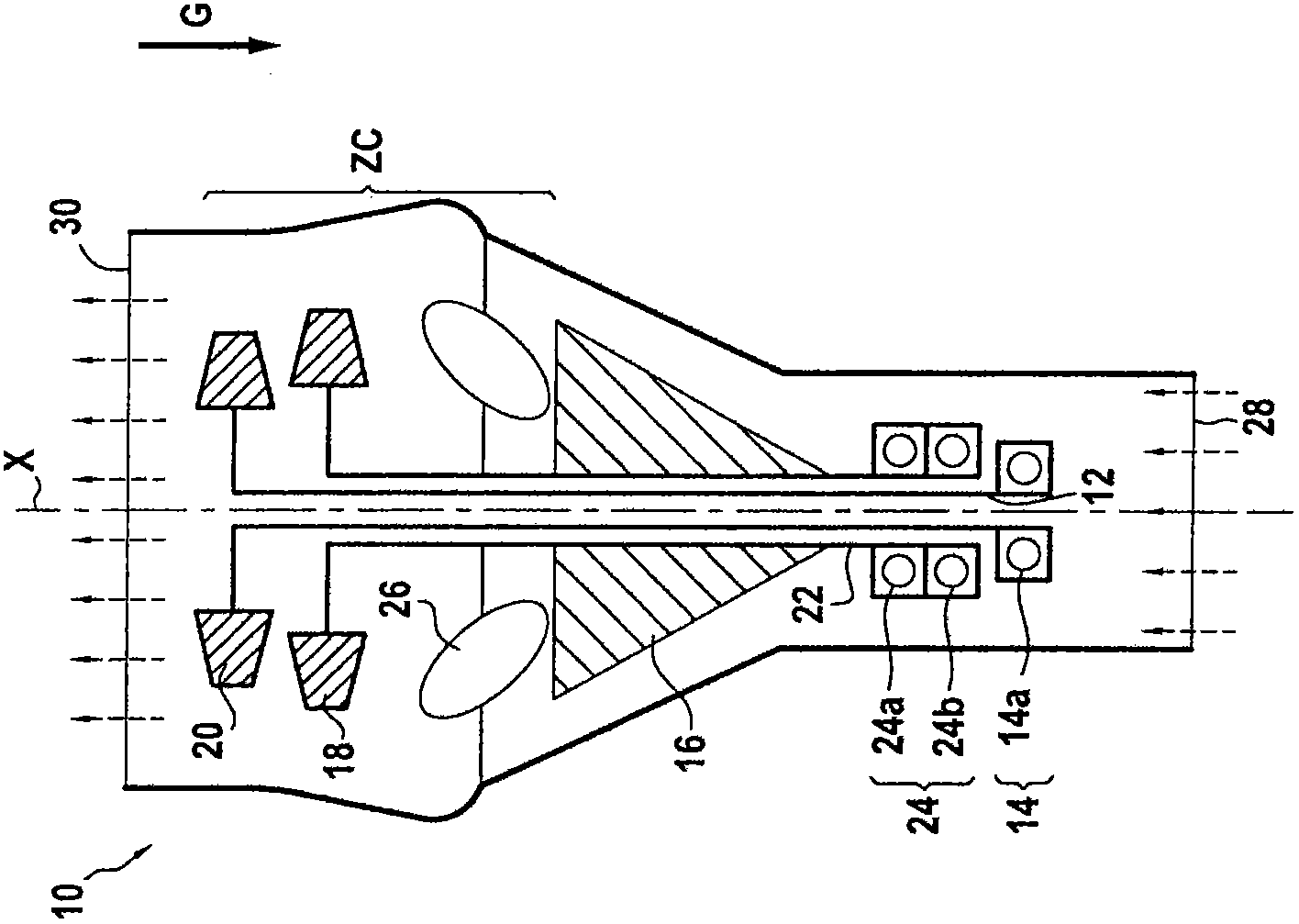
[0036] FIG. 1 shows a first exemplary embodiment of a turbomachine 10 in a schematic longitudinal section on the axis X of the turbomachine 10 . The axis X of the turbomachine 10 adopts a vertical orientation, ie parallel to the direction of gravity G indicated by the thick arrow. The dashed arrows indicate the direction of gas flow through the turbomachine.

[0037] The turbomachine 10 includes a shaft 12 oriented vertically and supported by a single bearing 14, the turbomachine shown in normal use. The turbomachine 10 comprises a compressor 16, an associated turbine 18 and a free turbine 20, the shown shaft 12 forming a first shaft on which is mounted a turbine wheel forming part of the free turbine 20 and a single bearing 14 forming a first single bearing.

[0038] In the illustrated embodiment, the free turbine 20 and the connected turbine 18 each have only a single turbine wheel. Of course, in another way, both the connected turbine and / or the free turbine have multiple...


PUM


Abstract

A turbomachine includes a compressor, a first shaft, a second shaft, a first turbine, and a second turbine. The first shaft carries at least one turbine wheel belonging to one of the elements selected from the first and second turbines. The second shaft carries at least one turbine wheel belonging to the other element selected from the first and second turbines. The first and second shafts are oriented substantially vertically in normal utilization situations of the turbomachine. The first shaft is held by a first single bearing while the second shaft is held by a second single bearing.

Description

technical field [0001] The invention relates to the field of turbomachines. Background technique [0002] Typically, a turbomachine comprises at least one shaft connected to at least one turbine wheel (which may be a free turbine wheel or a connected turbine wheel), said shaft being arranged horizontally, i.e. with its axis oriented substantially perpendicular to the direction of gravity . To properly support the shaft and support its weight, a number of bearings, usually two, are provided along the shaft. For this purpose, in a turbomachine comprising a compressor, a combustion chamber and a turbine in succession from upstream to downstream, one bearing is arranged upstream of the compressor and the other bearing is located downstream of the combustion chamber. This setup has several drawbacks. [0003] The first drawback is that these shafts are usually long and heavy, and although each bearing provides a point of support, there is still a long section that cantilevers ...

Claims


Application Information

Patent Timeline
Patent Type & Authority Patents(China)
IPC IPC(8): F01D25/16F02C7/06
CPCF02C7/06Y02T50/671F01D25/16F05D2250/315F05D2220/329Y02T50/60
Inventor 弗雷德里克·巴特列
Owner TURBOMECA SA
Why Eureka
Try Eureka