Ratchet gear of screw driver and screw driver using ratchet gear

The technology of a ratchet device and a screwdriver is applied in the structure of a ratchet screwdriver and the field of the ratchet device of a screwdriver, which can solve the problems of high production cost and complex structure of the ratchet mechanism, and achieve the effects of long service life, simplified structure and reduced cost.

Active Publication Date: 2012-11-21
ZHEJIANG SANDING TOOLS
View PDF9 Cites 21 Cited by
  • Summary
  • Abstract
  • Description
  • Claims
  • Application Information

AI Technical Summary

Problems solved by technology

[0005] In order to solve the technical defects of the above-mentioned ratchet mechanism with complex structure and high production cost, an object

Method used


Image

  • Ratchet gear of screw driver and screw driver using ratchet gear
  • Ratchet gear of screw driver and screw driver using ratchet gear
  • Ratchet gear of screw driver and screw driver using ratchet gear

Examples


Embodiment Construction

[0027] The specific implementation manner of the present invention will be described in detail below in conjunction with the accompanying drawings.

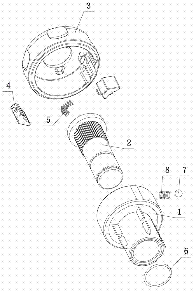
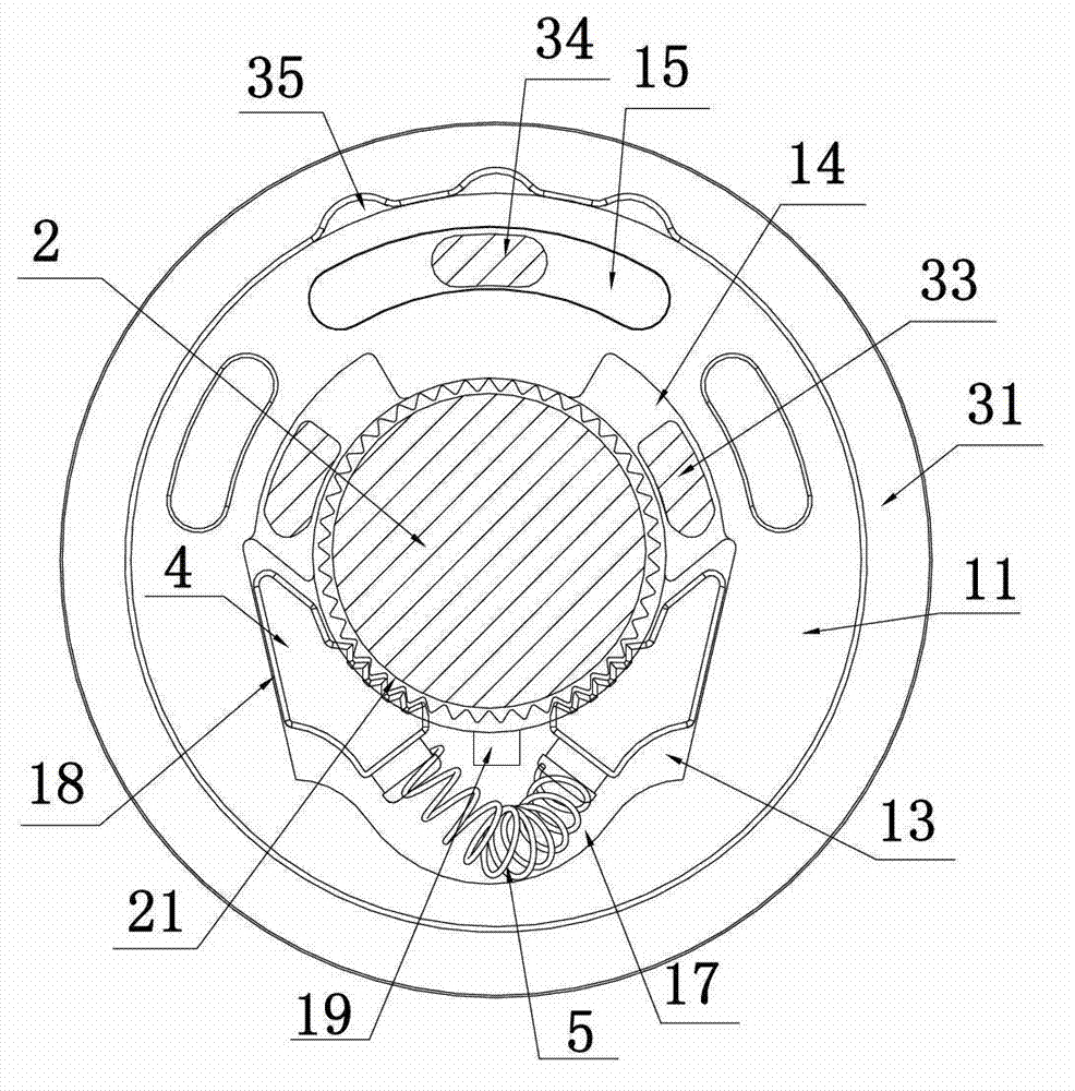
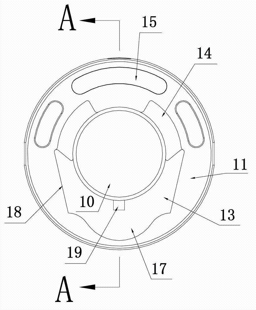
[0028] Such as figure 1 , figure 2 A screwdriver ratchet device is shown. The ratchet device includes a ratchet seat 1 , a ratchet shaft 2 , an outer collar 3 and two ratchets 4 . A first central shaft hole 10 is provided in the axial direction of the ratchet seat 1 . The front end of the ratchet seat 1 is an annular body 11 , and the rear end is a connecting portion 12 for connecting the screwdriver handle body. The outer collar 3 is composed of an annular bottom surface 31 and an annular outer ring 32 , the annular outer ring 32 is sheathed on the outer ring of the annular body 11 , and the annular bottom surface 31 is provided with a second central axis hole 30 . Such as Figure 7 , Figure 8 As shown, a connection port 24 is provided in the middle of the outer end of the ratchet shaft 2, and a magnetic steel 25 is provid...


PUM


Abstract

The invention relates to a structure of a screw driver with a ratchet gear, in particular to the ratchet gear of the screw driver and the screw driver using the ratchet gear. The ratchet gear of the screw driver comprises a pawl seat, a ratchet shaft, an outer clamping ring and two pawls. When the ratchet gear is located at a locking state normally, and the outer clamping ring is rotated in a clockwise direction, a toggling protrusion pushes the left pawl to move outwards along the first inclined surface so as to enable the ratches on the left pawl and a strip tooth to demesh; when the ratchet gear is located in an anticlockwise rotation state, and the outer clamping ring is rotated in an anticlockwise direction, the toggling protrusion pushes the right pawl to move outwards along the first inclined surface so as to enable the ratches on the right pawl and the strip tooth to demesh; and the ratchet gear is located at a clockwise rotation state. The invention has the characteristics that the structure of the ratchet gear is simplified, the production cost is reduced, and the service life is long.

Description

technical field [0001] The invention relates to a structure of a ratchet screwdriver, in particular to a screwdriver ratchet device and the use of the ratchet device and a screwdriver. Background technique [0002] Existing screwdrivers are all fixed with a metal main rod at the front end of the handle, and the free end of the main rod is provided with a cross or a straight-shaped wrenching part. The wrenching part rotates so as to loosen and tighten bolts. When using this kind of screwdriver, the user needs to keep loosening and tightening the palm so that the palm is in a position where it is easy to apply force to smooth the teeth, and the grip and the wrenching part are integrated, so the user must constantly loosen and tighten the screwdriver. It is very inconvenient to operate with the palm of your hand. [0003] In order to solve the above-mentioned technical problems, there has been a ratchet screwdriver, such as the ratchet mechanism of a screwdriver disclosed in ...

Claims


Application Information

Patent Timeline
IPC IPC(8): B25B15/04B25B23/16
Inventor 徐志明
Owner ZHEJIANG SANDING TOOLS
Why Eureka
Try Eureka