Gas nailing tool

A tool and gas technology, applied in nailing tools, manufacturing tools, etc., can solve the problems of narrowing the scope of use, complex manufacturing, increasing manufacturing costs, etc., and achieve the effects of low nailing cost, ingenious structural design, and simple manufacturing and installation.

Inactive Publication Date: 2012-11-21
朱益民
View PDF7 Cites 0 Cited by
  • Summary
  • Abstract
  • Description
  • Claims
  • Application Information

AI Technical Summary

Problems solved by technology

[0003] At present, the existing gas nailing tool mainly includes housing 1, cylinder head, cylinder liner combination, cylinder body, piston striker combination, gun head 2 with gun barrel, conical spring, safety frame, ejector rod and trigger handle, The gas nailing tool with such a structure, in order to make room for the installation space for the pressure spring of the safety frame, without changing the length of the housing, the length of the cylinder block must be shortened (such as figure 1 ), in this way, the total stroke of the piston striker is greatly shortened, and the nailing force is reduced by more than 10%.
In order to obtain sufficient nailing force and at the same time give way to the installation space for the pressure spring of the insurance frame, many manufacturers use the method of extending the length of the shell to achieve it (such as figure 2 ), however, doing so will cause the overall length of the gas nailing tool to be lengthened by at least 20mm, which not only increases the manufacturing cost, but also tends to yaw from left to right during the nailing operation, resulting in inaccurate nailing
In order to solve the above-mentioned defects, many manufacturers adopt the method of setting the pressure spring of the safety frame outside the casing, but after the pressure spring of the safety frame is arranged outside the casing, the safety frame is arranged on the barrel, which not only makes the It is relatively complicated and has a lot of consumables, which leads to an increase in cost. Moreover, because the barrel of the gas nailing tool is limited by the safety frame, it cannot hit the insulation nails used to fasten the insulation wall, which reduces the scope of use.
[0004] In order to be able to hit the insulation nails, some manufacturers have specially manufactured nailing tools that can hit the insulation nails, but such nailing tools use gunpowder as fuel. , using gunpowder as fuel, each nail needs 0.24 yuan, resulting in higher cost

Method used


Image

  • Gas nailing tool
  • Gas nailing tool
  • Gas nailing tool

Examples


Embodiment 1

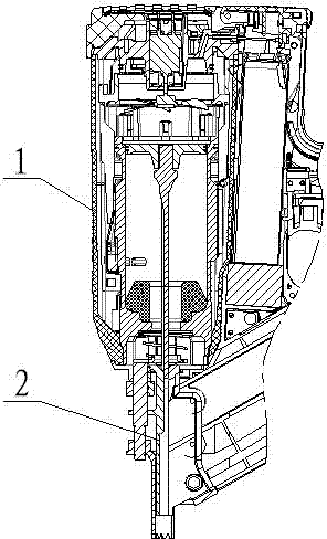
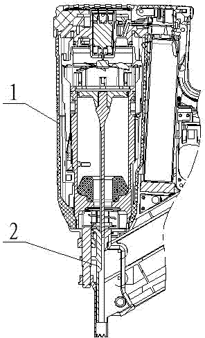
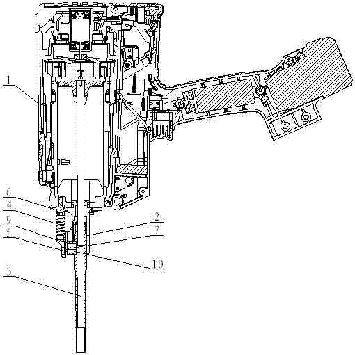
[0016] Embodiment 1: as image 3 , 4 As shown in , 5, a gas nailing tool includes a housing 1, a gun head 2, a gun barrel 3, a safety bracket clip spring 4 and a safety bracket 5, and the gun head 2 is connected to the front end of the housing 1 through a disc 6. connected, the gun head 2 and the gun barrel 3 are split, one end of the gun barrel 3 penetrates into the gun head 2 and is anti-rotated by the anti-rotation device, and the safety bracket clip spring 4 and the safety bracket 5 are connected to the the end.

[0017] Further description, the anti-rotation device is a boss 7 arranged on the outer wall of one end of the gun barrel 3 and an opening groove 8 arranged on the gun head 2, the boss 7 is located in the opening groove 8, and the safety frame One end of stage clip 4 is connected with boss 7 by spring seat 9 and screw 10, and the other end is connected with disc 6, and the bottom of described safety bracket 5 is positioned between spring seat 9 and boss 7, and i...


PUM


Abstract

The invention discloses a gas nailing tool. The gas nailing tool comprises a shell (1), a gun head (2), a gun barrel (3), a safety support pressure spring (4) and a safety support (5). The gun head (2) is connected with the front end of the shell (1) through a disk (6), the gun head (2) and the gun barrel (3) are split, and the safety support pressure spring (4) and the safety support (5) are both connected to one end of the gun barrel (3) which penetrates into the gun head (2) and is prevented from rotating through a rotation preventing device. The gas nailing tool has the advantages of ingenious structural design and simplicity in manufacturing and mounting, using the gas nailing tool without increasing the length of the shell can not only obtain enough striking force but also realize wider utilization range and low nailing cost, and utilization cost is greatly saved.

Description

[0001] technical field [0002] The invention relates to a tool which uses liquefied gas to burn in a combustion chamber through electric shock discharge to drive a piston striker to drive a fastener into a working surface. Background technique [0003] At present, the existing gas nailing tool mainly includes housing 1, cylinder head, cylinder liner combination, cylinder body, piston striker combination, gun head 2 with gun barrel, conical spring, safety frame, ejector rod and trigger handle, The gas nailing tool with such a structure, in order to make room for the installation space for the pressure spring of the safety frame, without changing the length of the housing, the length of the cylinder block must be shortened (such as figure 1 ), in doing so, the total stroke of the piston striker is greatly shortened, and the nailing force is reduced by more than 10%. In order to obtain sufficient nailing force and at the same time give way to the installation space for the pr...

Claims


Application Information

Patent Timeline
Patent Type & Authority Applications(China)
IPC IPC(8): B25C1/08
Inventor 朱益民
Owner 朱益民
Why Eureka
Try Eureka