Valve lift continuous variable mechanism of engine gas distribution system

A technology of valve lift and engine, which is applied in the direction of engine components, engine control, combustion engine, etc., can solve the problems that the valve cannot be changed, the power performance of the engine cannot be fully exerted, and the valve cannot be controlled, so as to reduce fuel consumption and emission indicators and facilitate Effects of cabin layout and improved economy

Active Publication Date: 2012-11-21
GREAT WALL MOTOR CO LTD
View PDF5 Cites 6 Cited by
  • Summary
  • Abstract
  • Description
  • Claims
  • Application Information

AI Technical Summary

Problems solved by technology

Since the VVT ​​technology cannot change the degree of valve opening, that is, it cannot control the change of the valve lift, it is difficult to better adapt to the complex and changeable working conditions of the engine, and it is not optimal for the improvement of fuel consumption and emissions. The dynamic performance cannot be fully exerted
In response to the above situation, some automobile engines currently use a continuously variable valve lift valve system (VVL technology), but due to the complex structure, the height of the engine is increased, which is not conducive to the layout of the engine on the vehicle

Method used


Image

  • Valve lift continuous variable mechanism of engine gas distribution system
  • Valve lift continuous variable mechanism of engine gas distribution system
  • Valve lift continuous variable mechanism of engine gas distribution system

Examples


Embodiment Construction

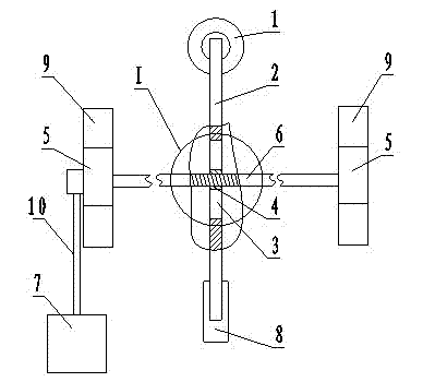
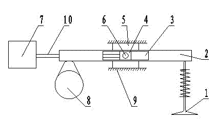
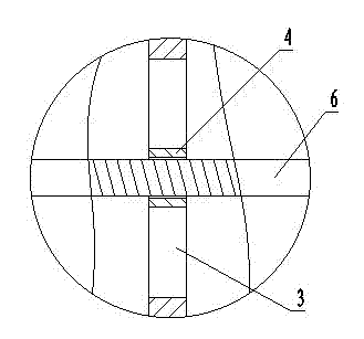
[0017] See Figure 1, Figure 2, image 3 , the present invention includes a group of valve lift continuous change control units whose number matches the number of engine cylinders, wherein each valve lift continuous change control unit is provided with a camshaft 8, a rocker arm 2, a rocker arm shaft 6 and a valve 1, Its special feature is that the slider I4 is installed in the middle of the rocker shaft 6, the slider I4 is hinged with the rocker shaft 6, and the rocker guide rail 3 with a cavity structure is provided in the middle of the rocker arm 2. The slider I4 can slide in the rocker guide rail 3.

[0018] See Figure 1, Figure 2, image 3 , the two ends of the rocker shaft 6 of the present invention are assembled with the slider II5 arranged symmetrically on both sides of the rocker arm 2 respectively, and the slider II5 is assembled with the cylinder head guide rail 9 arranged on the engine cylinder head, and the slider II5 Can slide along cylinder head guide rail 9. ...


PUM


Abstract

The invention relates to a valve lift continuous variable mechanism of an engine gas distribution system; the mechanism is used for realizing the continuous changes of the valve lift of an engine, and comprises a group of valve lift continuous change control units with the number matched with that of engine cylinders, wherein each valve lift continuous change control unit is provided with a cam, a rocker, a rocker shaft and a valve; and the mechanism is characterized in that a slider I is sleeved in the middle of the rocker shaft, the slider I is hinged with the rocker shaft, the middle part of the rocker is provided with a rocker guide rail in a cavity structure, and the slider I can slide in the rocker guide rail. According to the valve lift continuous variable mechanism of the engine gas distribution system, when the molded line of the cam is unchanged, the valve lift can be changed continuously, so that the purpose of matching with the complicated changeable working conditions of the engine is achieved, the oil consumption and the emission indicator of the engine are reduced, and the dynamic performance is fully displayed. The valve lift continuous variable mechanism of the engine gas distribution system has a wide scope of application, is matched with the variable-valve-timing (VVT) system of the engine, realizes the application of gas distribution phase and the fully variable technology of the valve lift, has a compact structure, and is convenient for the deployment of the engine in a cabin.

Description

technical field [0001] The invention relates to a valve lift continuous change control mechanism of an engine gas distribution system, which belongs to the technical field of engines. Background technique [0002] With the increasing consumption of global oil resources, countries around the world have put forward more and more stringent energy consumption and emission requirements to maximize the fuel thermal efficiency of automobile engines and improve fuel economy, so as to slow down excessive energy consumption and extend the service life of oil energy. Become the goal pursued by the current global automotive industry. [0003] Improving the charging efficiency of the engine is an effective way to improve its thermal efficiency and power. The VVT ​​technology that has been used in many engines is to adjust the phase of the intake and exhaust valves according to the different working conditions of the engine, that is, to adjust the intake and exhaust valves. The opening a...

Claims


Application Information

Patent Timeline
Patent Type & Authority Applications(China)
IPC IPC(8): F01L13/00F02D13/02
CPCY02T10/18Y02T10/12
Inventor 崔亚彬于文斌高定伟
Owner GREAT WALL MOTOR CO LTD
Why Eureka
Try Eureka