Stationary chain guide

A guide device and engine technology, which is applied in transmission devices, mechanical equipment, belts/chains/gears, etc., can solve problems such as deflection and deformation in the length direction of the bottom plate guide device, breakage of bolt installation positions, and complicated manufacturing, and achieve excellent durability properties, improving board strength, and suppressing deflection deformation

Inactive Publication Date: 2012-11-21
TSUBAKIMOTO CHAIN CO
View PDF6 Cites 0 Cited by
  • Summary
  • Abstract
  • Description
  • Claims
  • Application Information

AI Technical Summary

Problems solved by technology

[0005] However, this existing fixed guide, whose guide rail and bottom plate maintain a predetermined curvature along the length of the guide so as to properly maintain the chain track, is often loaded with excessive pressing load from the transmission chain, so even if it is made of If the bottom plate made of steel plate is used for a long time, there may be the following situations: the bottom plate will be deflected and deformed along the length direction of the guide device, and the bolt installation position of the engine mounting bolt will be broken. In addition, if you try to increase the strength of the bottom plate To prevent the deflection deformation and breakage of the above-mentioned bottom plate, there are complicated problems such as manufacturing a complicated base shape or using high-strength materials. Constraints that can't be realized

Method used


Image

  • Stationary chain guide
  • Stationary chain guide
  • Stationary chain guide

Examples


Embodiment 1

[0060] Next, a fixed guide device for an engine according to a first embodiment of the present invention will be described based on the drawings.

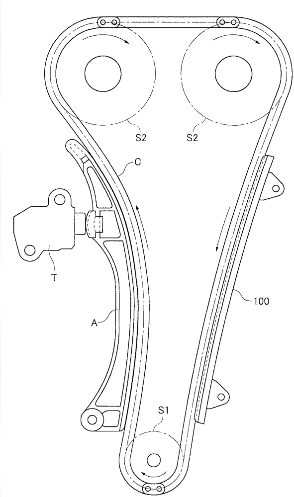
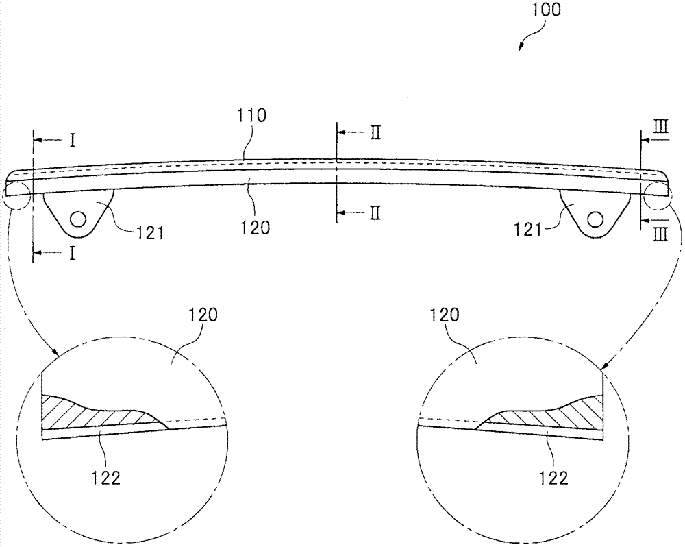
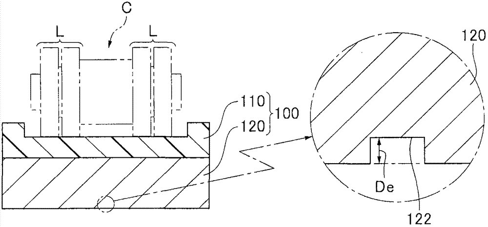
[0061] here, figure 1 It is a usage diagram of the fixed guide device for the engine of the first embodiment of the present invention, figure 2 yes figure 1 The schematic and partial enlarged view of the fixed guide for the engine shown, image 3 is in figure 2 The cross-sectional view and partial enlarged cross-sectional view of the I-I line, Figure 4 is in figure 2 The sectional view and partial enlarged view of the II-II line, Figure 5 is in figure 2 Sectional view and partial enlarged view of line III-III.

[0062] First, if figure 1 As shown, the engine fixed guide device 100 of the first embodiment of the present invention is used together with the following components in the timing system of the automobile engine. The components are the driving side sprocket S1 in the engine; the driven side chain in the engine...

Embodiment 2

[0077] Next, a fixed guide device for an engine according to a second embodiment of the present invention will be described based on the drawings.

[0078] here, Figure 6 It is a schematic view and a partially enlarged view of a fixed guide device for an engine according to a second embodiment of the present invention, Figure 7 is along Figure 6 The sectional view and partial enlarged view of the IV-IV line, Figure 8 is along Figure 6 The cross-sectional view and partial enlarged view of the V-V line, Figure 9 is along Figure 6 The cross-sectional view and partial enlarged view of the VI-VI line.

[0079] Compared with the fixed guide device 100 for the engine of the first embodiment, the fixed guide device 200 for the engine of the second embodiment of the present invention is only different in the structure of the thin groove part for reinforcement, and the structure of the remaining parts basically does not have any structure. As for the changes, the same compo...

Embodiment 3

[0083] Next, a fixed guide device for an engine according to a third embodiment of the present invention will be described based on the drawings.

[0084] here, Figure 10 It is a schematic view and a partially enlarged view of a fixed guide device for an engine according to a third embodiment of the present invention, Figure 11 is along Figure 10 Sectional view and partial enlarged view of line VII-VII. The engine fixed guide device 300 of the third embodiment of the present invention is compared with the engine fixed guide device 100 of the above-mentioned first embodiment, only the structure of the reinforcing thin groove part is different, and the structure of the remaining parts basically does not have any structure. As for the changes, the same components as those of the fixed guide device 100 for the above-mentioned engine are marked with the corresponding symbols of No. 300, and the repeated description thereof will be omitted.

[0085] The groove end 323 of the r...


PUM


Abstract

An elongated stationary guide for a traveling transmission chain in an engine such as a timing chain has a narrow reinforcing groove formed along the longitudinal direction of a metal base plate of the guide by surface-pressing (100), whereby the base plate exhibits plastic deformation. The narrow reinforcing groove (122) extends toward the ends of the base plate (120) past the locations at which the base plate (120) is mounted on an engine block by mounting bolts.

Description

technical field [0001] The present invention relates to a fixed guide device for an engine used in a timing system for an automobile engine for moving a transmission chain in a sliding contact manner. Background technique [0002] Conventionally, in a timing system for an automobile engine, as a fixed guide device for moving a transmission chain, that is, a timing chain, in a sliding contact manner, a drive-side sprocket and a driven-side chain in the engine are known. A fixed guide device that guides the movement of the timing chain that moves cyclically between the wheels in sliding contact along a predetermined chain track. [0003] Moreover, this fixed guiding device is equipped with: a guide rail (shoe), which is formed with a sliding contact curved surface that enables the transmission chain to move in a sliding contact manner along the longitudinal direction of the guiding device; On the back side of the guide rail, the above-mentioned guide rail and the bottom plate...

Claims


Application Information

Patent Timeline
Patent Type & Authority Applications(China)
IPC IPC(8): F16H7/18
CPCF16H2007/0872F16H7/18
Inventor 石川祐一郎早见淳志进谷忠司
Owner TSUBAKIMOTO CHAIN CO
Why Eureka
Try Eureka