Peeling test method and peeling test device
A peeling tester and peeling test technology, which is applied in the field of peeling tester and peeling test, can solve problems such as inaccurate peel strength value measurement, and achieve the effect of avoiding errors and accurate measurement
- Summary
- Abstract
- Description
- Claims
- Application Information
AI Technical Summary
Problems solved by technology
Method used
Image
Examples
Embodiment 2
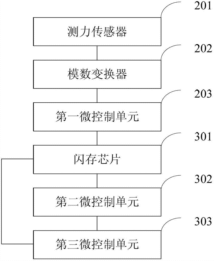
[0073] see image 3 , is a schematic structural diagram of a second peeling tester provided by an embodiment of the present invention, the peeling tester includes: a load cell 201, an analog-to-digital converter 202, a first micro-control unit 203, a flash memory chip 301, and a second micro-controller Unit 302, where:
[0074] The load cell 201 is connected to the analog-to-digital converter 202 , the analog-to-digital converter 202 is connected to the first micro-control unit 203 , the flash memory chip 301 is connected to the first micro-control unit 203 , and the second micro-control unit 302 is connected to the flash memory chip 301 .
[0075] The analog-to-digital converter 202 is used to convert the force value collected by the load cell 201 into a discrete digital signal;
[0076] The first micro-control unit 203 is used to sort the discrete digital signals according to the size of the discrete digital signal values, obtain the intermediate value of the sorting result...
Embodiment 3
[0086] see Figure 4 , is a schematic structural diagram of the adjustable shoe last in the above-mentioned peel tester disclosed in the embodiment of the present invention, and the adjustable shoe last includes:
[0087] Front fixing block 1, bolt 2, adjusting nut 3, rear fixing block 4, rear shoe last 5 and front shoe last 6, wherein:
[0088] The front fixing block 1 is arranged in the front shoe last 6, the front fixing block 1 is provided with a threaded hole, the rear fixing block 4 is arranged in the rear shoe last 5, the rear fixing block 4 is provided with a through hole, and the bolt 2 penetrates through the front. The threaded hole in the fixed block 1 and the through hole in the rear fixed block 4, the bolt 2 is used to connect the front fixed block 1 and the rear fixed block 4, the bolt 2 matches the threaded hole in the front fixed block 1, and the adjustment nuts are 3 sets It is arranged on the bolt 2 and is located between the front fixing block 1 and the rea...
Embodiment 4
[0096] The embodiment of the present invention provides a peeling test knife in the above-mentioned peeling tester, and the peeling test knife includes:
[0097] The rib-shaped protrusions and the mounting holes at the end of the pressing surface of the peeling test knife.
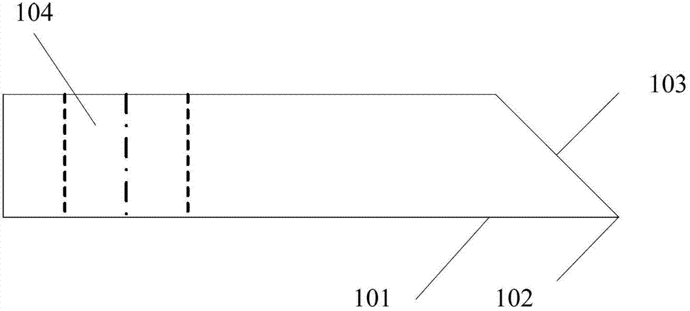
[0098] Preferably, the figure 1 The pressure surface is divided into three pressure surfaces: the first pressure surface, the second pressure surface and the third pressure surface. The relationship between the first pressure surface, the second pressure surface and the third pressure surface is as follows: Figure 5 to Figure 10 shown. Of course you can only Figure 5 to Figure 10 the end of the first pressing surface (ie figure 1 The end of the medium pressure surface 102) is improved, and the figure 1 The pressure surface is divided into a first pressure surface, a second pressure surface and a third pressure surface.
[0099] see Figure 5 , is a schematic structural diagram of the first peeling ...
PUM
| Property | Measurement | Unit |
|---|---|---|
| Central angle | aaaaa | aaaaa |
Abstract
Description
Claims
Application Information
 - R&D
- Intellectual Property
- Life Sciences
- Materials
- Tech Scout
- Unparalleled Data Quality
- Higher Quality Content
- 60% Fewer Hallucinations
Browse by: Latest US Patents, China's latest patents, Technical Efficacy Thesaurus, Application Domain, Technology Topic, Popular Technical Reports.
© 2025 PatSnap. All rights reserved.Legal|Privacy policy|Modern Slavery Act Transparency Statement|Sitemap|About US| Contact US: help@patsnap.com


