System for fastening a rail and guide plate for such a system

A technology for fixing rails and guide plates, applied in the field of systems for fixing rails and guide plates of such systems, can solve problems such as changes in the positions of elastic parts and adapters, and achieve the effect of preventing excessive extrusion

Inactive Publication Date: 2012-11-21
VOSSLOH WERKE GMBH
View PDF6 Cites 7 Cited by
  • Summary
  • Abstract
  • Description
  • Claims
  • Application Information

AI Technical Summary

Problems solved by technology

[0004] However, harsh conditions that arise in practice can lead to unintended changes in the position of the elastic parts and adapters

Method used


Image

  • System for fastening a rail and guide plate for such a system
  • System for fastening a rail and guide plate for such a system
  • System for fastening a rail and guide plate for such a system

Examples


Embodiment Construction

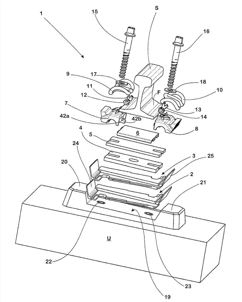
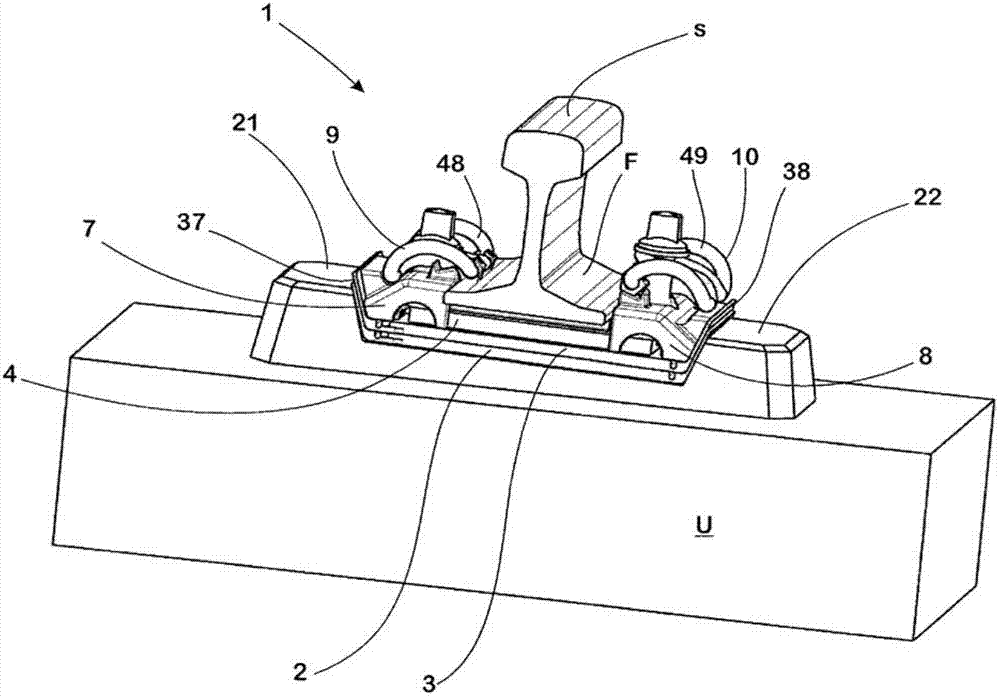
[0091] A system 1 for fixing a track S on a fixed base U formed, for example, of cement sleepers or cement slabs, the system comprising a first backing plate 2, a second backing plate 3, an elastic intermediate layer 4, a pressure distribution plate 5, a height Adjustment plate 6, first guide plate 7, second guide plate 8, two elastic parts 9, 10 formed as ω-shaped clamping clips, two pairs of adapters 11-14 and two clamps formed as clamping bolts Clamping elements 15 , 16 act on the central rings of the spring elements 9 , 10 via washers 17 , 18 .

[0092] The fastening system 1 is seated in a receptacle 19 formed in one piece on the fastening base, which is delimited on its narrow side extending parallel to the rail S by support shoulders 20 , 21 . In the bearing surface of the receptacle 19 present between the support shoulders 20 , 21 , plastic pins 22 , 23 are respectively inserted into the base U adjacent to the support shoulders 20 , 21 . When assembling the system 1 ,...


PUM


Abstract

The invention relates to a system for fastening a rail on a subsurface (U) and to a guide plate (7, 8) intended for such a system (1). The system comprises a spring element (9, 10) which can be braced against the subsurface (U) by means of a tensioning element (15, 16) and has at least one spring arm (48, 49), an adapter piece (11-14) which sits on an end section of the spring arm (48, 49) and has a contact surface section (58-60), and a guide plate (7, 8). The guide plate has a contact surface (42) for the rail foot (F) and a slide surface (56, 57) which adjoins the contact surface (42) and via which the adapter piece (11-14) can be moved out of a pre-assembly position, in which the contact surface section (58-60) of the adapter piece sits on the guide plate (7, 8), into an installation position, in which the contact surface section (58-60) of the adapter piece sits on the rail foot (F) of the rail (S) to be fastened. The slide surface (56, 57) of the guide plate (7, 8) ascends in the direction of the contact surface (42). In addition, a stop (54, 55) is provided on the slide surface (56, 57) and the adapter piece (11-14) is seated against said stop in the pre-assembly position.

Description

technical field [0001] The invention relates to a system for fixing rails, wherein the system has an elastic part which can be clamped relative to a base by clamping means, the elastic part has at least one spring arm, and an adapter part, which is located on the elastic part The end of the spring arm, wherein the adapter has a joint surface section formed on its periphery, also has a guide plate, which has a joint surface on its front side corresponding to the rail foot, and has an abutment on its free upper side The sliding surface of the mating surface, through which the adapter is advanced from the pre-assembly position (in which the adapter rests on the guide plate with its The joint surface is seated on the rail foot of the track to be fixed), so that the elastic force exerted by the elastic member is transmitted to the rail foot. [0002] The invention also relates to the guide plate used in this system. Background technique [0003] A system of the aforementioned t...

Claims


Application Information

Patent Timeline
Patent Type & Authority Applications(China)
IPC IPC(8): E01B9/30
CPCE01B9/30E01B9/303E01B9/483
Inventor 温弗里德·博斯特林阿德里安·贝德纳尔奇克安德烈·胡诺尔德妮科尔·维特霍夫
Owner VOSSLOH WERKE GMBH
Why Eureka
Try Eureka