Method of bonding a metal to a substrate

A substrate, metal technology, applied in the direction of metal material coating process, nanotechnology, coating, etc.

Inactive Publication Date: 2012-11-28
GM GLOBAL TECH OPERATIONS LLC
View PDF7 Cites 10 Cited by
  • Summary
  • Abstract
  • Description
  • Claims
  • Application Information

AI Technical Summary

Problems solved by technology

The presence of lighter weight materials reduces the overall weight of automotive parts in some cases

Method used


Image

  • Method of bonding a metal to a substrate
  • Method of bonding a metal to a substrate
  • Method of bonding a metal to a substrate

Examples


Embodiment Construction

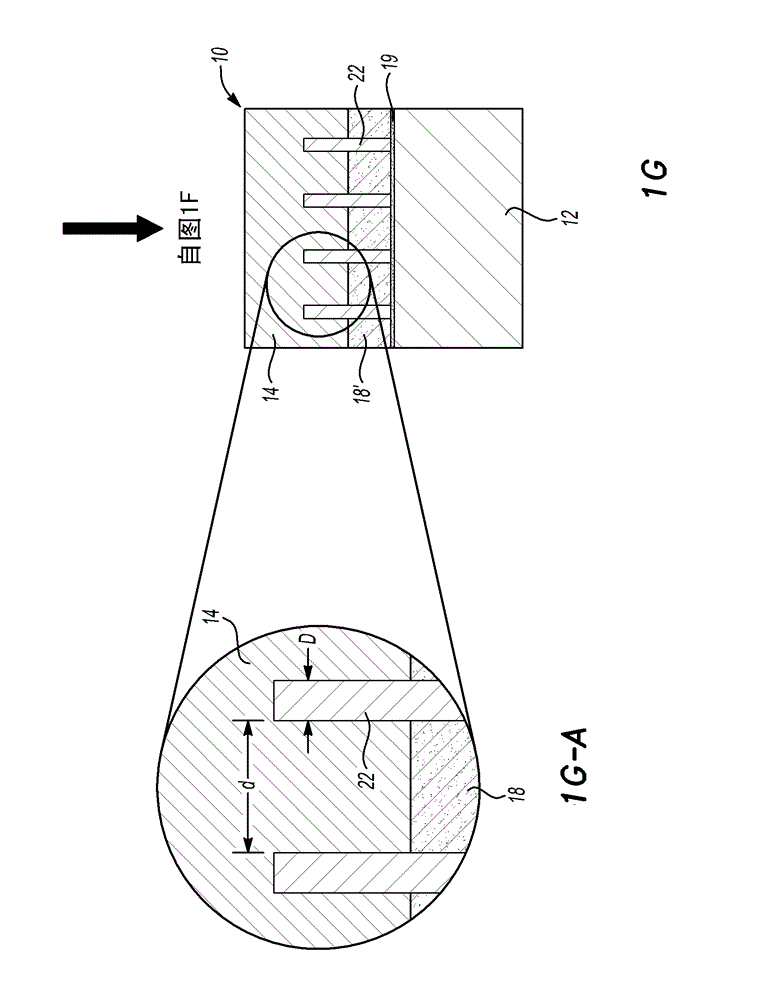
[0038] Aluminum and steel can be used to make different automotive parts, at least because these materials have mechanical strength that contributes to the structural integrity of the part. It has been found that some of the aluminum or steel in the part can be replaced with a lighter weight material such as magnesium. It is believed that the presence of magnesium reduces the overall weight of the automotive part in some cases.

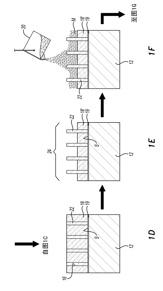
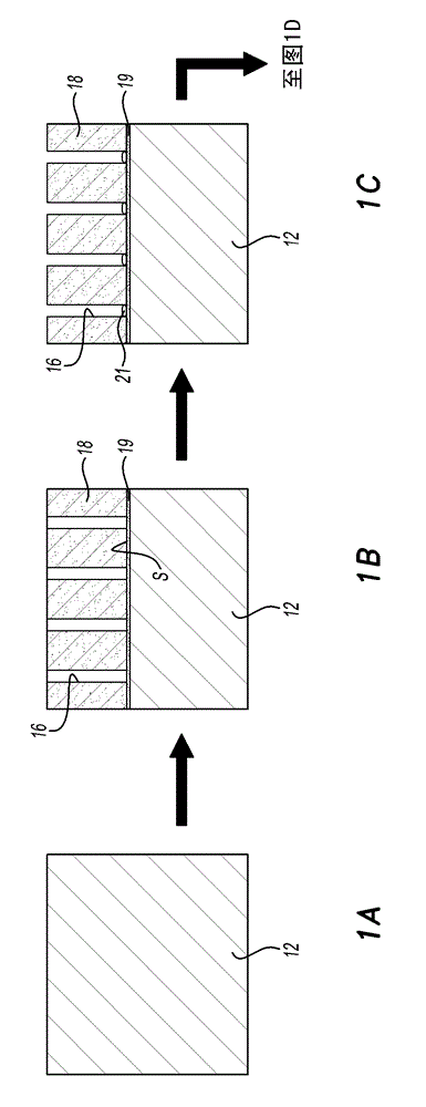
[0039] It has been found that magnesium can be incorporated onto aluminum or steel parts via casting methods such as the method known as flood casting. It has also been found that in some cases magnesium cannot metallurgically bond to the underlying aluminum or steel, at least not to the extent necessary to form parts that are considered structurally sound and usable for automobiles. For example, aluminum may include a dense oxide surface layer (e.g., alumina) formed thereon that prevents metallurgical bonding of magnesium to the aluminum underlying ...


PUM

PropertyMeasurementUnit
diameteraaaaaaaaaa
melting pointaaaaaaaaaa

Abstract

A method of bonding a metal to a substrate is disclosed herein. The method involves forming a nano-brush on a surface of the substrate, where the nano-brush includes a plurality of nano-wires extending above the substrate surface. In a molten state, the metal is introduced onto the substrate surface, and the metal surrounds the nano-wires. Upon cooling, the metal surrounding the nano-wires solidifies, and during the solidifying, at least a mechanical interlock is formed between the metal and the substrate.

Description

[0001] Cross-Referenced Related Applications [0002] This application claims the benefit of US Provisional Patent Application Serial No. 61 / 488995, filed May 23, 2011. technical field [0003] The present invention generally relates to methods of bonding metals to substrates. Background of the invention [0004] Many automotive parts are made, for example, of aluminum or steel. In some cases, it may be desirable to replace at least a portion of the aluminum or steel parts with lighter-weight materials such as magnesium. The presence of lighter weight materials can in some cases reduce the overall weight of the automotive part. Contents of the invention [0005] Methods of bonding metals to substrates are disclosed herein. The method includes forming a nano-brush on a substrate surface, where the nano-brush includes a plurality of nano-wires extending above the substrate surface. The metal in a molten state is introduced onto the surface of the substrate, and the meta...

Claims


Application Information

Patent Timeline
Patent Type & Authority Applications(China)
IPC IPC(8): B22D19/08B22D19/16
CPCB22D19/08C23C6/00Y10S977/762Y10S977/781Y10S977/89Y10S977/891Y10T428/12444
Inventor M.J.沃克B.R.小鲍威尔
Owner GM GLOBAL TECH OPERATIONS LLC
Why Eureka
Try Eureka