Power-assisted bicycle using sensor with position-adjustable magnetic blocks in casing

A technology for assisting bicycles and sensors, which is applied in the use of electric/magnetic devices to transmit sensing components, convert sensor outputs, instruments, etc., can solve the problems of lack of control signals, inability to have both, and permanent magnets unable to indicate the rotation position of the pedals.

Active Publication Date: 2012-11-28
JIANGSU PROVINCE SINGE IRRIGATION & DRAINAGE EQUIP
View PDF5 Cites 2 Cited by
  • Summary
  • Abstract
  • Description
  • Claims
  • Application Information

AI Technical Summary

Problems solved by technology

[0015] Disadvantages (1) Using two permanent magnets with no difference to represent the fixed positions of the two pedals, only multiple Halls can be used to represent the pedals Rotation position: There is no difference between the two permanent magnets. The advantage is that the fixed positions of the two pedals can be expressed regardless of the left and right feet, so that the left and right feet can generate power assistance requirements, which can produce the same motor power assistance effect; but the disadvantage is that The permanent magnetic steel itself cannot indicate the rotation position of the pedal, but can only use multiple Halls at different corner positions to indicate the rotation position of the pedal, so it is not possible to use only one Hall, but must use multiple Halls
[0016] Disadvantage (2) Only one Hall cannot be used, but three Halls will inevitably cause the original segmentation error of the three control signals, which will distort the power-assist demand model, naturally The generation of power output is inconsistent with the demand for power assistance: no matter whether the power-assisted bicycle has one or two motors, the sensor signal for controlling the motor can only be controlled by using one sensor signal input to the motor controller; and the patent uses three sensors. If Hall controls the motor, the three control signals of the three Halls must be combined into one combined control signal before it can be input to the motor controller
The sensing parameters of the three Halls cannot be the same, especially due to changes in ambient temperature and long-term use, the sensing parameters of the three Halls may vary greatly. The output voltages are different, resulting in different power output of the motor, and the power output is inconsistent with the power demand; similarly, when the power demand is the same, the outputs of different Halls may be the same voltage, resulting in the same power output of the motor, and also There is a problem that the power output is inconsistent with the power demand
[0017] Disadvantages (3) The combined control signal is prone to signal drift, which makes the combined control signal not match the motor controller, and the power-assisted demand model is distorted: due to changes in ambient temperature and use time After a long period of time, the sensing parameters of the three Halls may vary greatly, and the connection points of the three control signals of the three Halls will inevitably change, so the combined control signals generated by the same boosting demand will produce segmental signal drift. Combining the control signals as a whole produces signal distortion, that is, the power-assist demand model is distorted, causing the motor controller to choose any one of the three control signals as a reference, resulting in the inconsistency between the power-assisted output and the power-assisted demand
[0018] Disadvantage (4) The sensing points cannot be increased arbitrarily. If there are too few sensing points, the motor will not run smoothly, making the rider feel very uncomfortable: due to the disadvantages (1) and (2) are the most important The number of halls is greater than one. Obviously, the more the number of halls, the more serious the shortcomings (1) and (2) are.
Therefore, the power-assisted bicycle provided by this patent can only be a very bad power-assisted bicycle that makes the rider feel comfortable.
[0019] Disadvantages (5) The signal blind area reaches 42 degrees, and when the power is needed when starting, it is impossible to get it: as we all know, the torque of the bicycle pedal is the smallest at the apex , from the angle of 10-45 degrees away from the top is the area that needs the most assistance, but the angle between the Halls in this patent is 42.5-43.5 degrees, and there is no Hall in the area of ​​10-42 degrees away from the top of the pedal. There is no control signal, and the result is when the assist is most needed, but the motor of the assist bicycle cannot assist
[0020] In short, this patent is a technical solution for using multiple Halls to control the booster mode, because only multiple Halls can be used to represent the rotation position of the pedal, and the multiple control signals of multiple Halls must have original errors, and the combined control signals It is also easy to produce signal drift, which can cause distortion of the assist demand model, that is, the same assist demand at different times, but different assist effects; the more the number of Halls, the more serious the distortion of the assist demand model, limiting the number of Halls , a small amount of Hall will cause the motor to run unsteadily, making the rider feel very uncomfortable, and will not get assistance when starting
To make it undistorted to help the demand model, and to ensure the smooth operation of the motor, there are always two issues. It is impossible to have both.

Method used


Image

  • Power-assisted bicycle using sensor with position-adjustable magnetic blocks in casing
  • Power-assisted bicycle using sensor with position-adjustable magnetic blocks in casing
  • Power-assisted bicycle using sensor with position-adjustable magnetic blocks in casing

Examples


Embodiment 1

[0134] Embodiment 1. A power-assisted bicycle with adjustable sensors in the position of multiple magnetic blocks in the housing

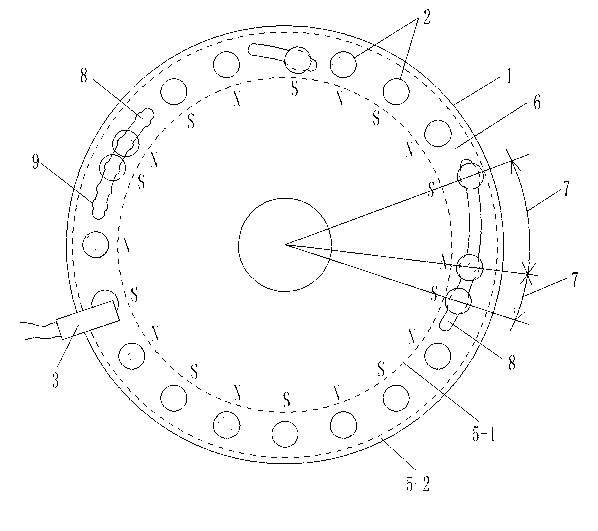
[0135] Such as figure 1 , 3 , 4, 6, the sensor among the present invention is installed on the central axis 51 of existing electric bicycle, the signal output line of sensor is connected with the motor controller 29 of electric bicycle, just obtains power-assisted bicycle of the present invention.

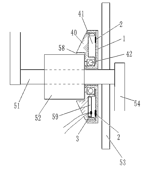
[0136] 1. The components and structure of the electric bicycle related to the installation of the sensor: the electric bicycle has a central shaft 51, and the middle section of the central shaft 51 is covered with a bushing 52, and the central shaft 51 is connected to the bushing 52 in rotation; the chain disc 53 is fixed on the central shaft 51 The two ends of the central axis 51 are respectively fixed with pedals 54; the inner surface of the casing 52 is connected to the central axis 51 in rotation, and the outer surface of the casing 52 is fixedly ...

Embodiment 2

[0161] Embodiment 2, a power-assisted bicycle with adjustable sensors for multiple magnetic blocks in the housing for high density

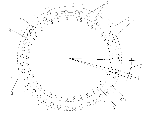
[0162] Such as figure 2 , 3, 4, 6, the diameter of the annular groove rotating disk 1 in the hollow ring 41 is 10.0 centimeters, and 40 permanent magnet blocks 2 are established at the annular groove rotating disk 1, and the diameters of the 40 permanent magnet blocks 2 are respectively 0.6 centimeters, The magnetic flux is 146---279(B·H)max / KJ·m -3 one of the values ​​in . Hall 3 keeps a distance of 0.2 cm from each permanent magnet 2 in the rotating state, so that when each rotating permanent magnet 2 passes through Hall 3, Hall 3 can generate a corresponding rectangular wave electric signal output. The circle where the arc of the arc-shaped bar-shaped short groove 8 is located and the inner circular locus 5-1 are concentric circles. The structures of other rotating disk 1, permanent magnet block 2, and Hall 3 are the same as those in embo...

Embodiment 3

[0163] Embodiment 3. A power-assisted bicycle with adjustable sensors for multiple magnetic blocks in the housing with a specific circuit

[0164] Such as figure 1 , 3 , 5, 6, as in embodiment 1, the sensor includes a sensing element connected in sequence, a booster model processor 21, a digital-to-analog converter 27 and an operational amplifier 28;

[0165] [1] The Hall 3 in the sensing element is UGN3075; the structure of other elements and elements in the sensing element is the same as that in Embodiment 1;

[0166] [2] The auxiliary model processor 21 selects the single-chip microcomputer 31 to complete all functions, and the single-chip microcomputer 31 selects AT89S52. That is, the AT89S52 single-chip microcomputer 31 completes all functions of the analog-to-digital conversion and the wave width identifier 22 , the power-assisted starting point selector 23 , the magnet speed calculator 24 , the power-assisted model memory 25 and the power-assisted model calculator 26...


PUM


Abstract

The invention discloses a power-assisted bicycle using a sensor with position-adjustable magnetic blocks in a casing, which belongs to an electrically power-assisted bicycle for providing power-assisted signals through multi-point-position magnetic induction. The sensor comprises a sensing element, a power-assisted model processor, a D / A (digital to analog) converter and an operational amplifier which are sequentially connected, wherein the sensing element comprises permanent magnet blocks and a hall arranged in an inner cavity formed by that a movable plate and a fixed plate are mutually embedded, the movable plate is provided with a plurality of permanent magnet blocks, wherein two adjacent permanent magnet blocks are opposite in magnetic polarity, and the distance between the permanent magnet blocks can be adjusted, and the hall on the fixed plate is arranged at a position close to the permanent magnet blocks. The sensor is sleeved outside of a middle axle of the bicycle, and the operational amplifier is connected with a motor controller. The power-assisted bicycle disclosed by the invention has the advantages that: the relative positions between the permanent magnet blocks and the hall are fixed, and the hall can acquire rectangular wave signals, thereby facilitating that the sensor outputs reasonable forces (which are artificially set and can be adjusted) from the power-assisted model to a power-assisted starting point and a power-assisted ending point through digital processing, so that the man-machine cooperation can be optimal, and an effect of power saving can be achieved.

Description

technical field [0001] The invention belongs to the technical field of power-assisted bicycles, in particular to an electric power-assisted bicycle that performs multi-point magnetic induction on a rotating part to provide power-assisted signals. Background technique [0002] The Chinese patent 201020295192.0 "Claw Type Torque Sensing Device" applied by Yebao Vehicle Material Industry (Kunshan) Co., Ltd. discloses a sensing device for power-assisted bicycles. The sensing device includes a magnetic part and an elastic part to sense the torque. sensing device. After a long time of use, the change of the elastic coefficient of the elastic member will lead to changes in the sensing signal and the control effect of the controlled motor, and the power-assisted effect will not match the power-assisted needs of people. Moreover, the design structure of the elastic member is complex and the manufacturing cost is high. [0003] The Chinese patent 01201843.0 "Automatic Detection Devi...

Claims


Application Information

Patent Timeline
IPC IPC(8): B62M6/50G01D5/244
CPCG01D5/246B62M6/50B62M6/65
Inventor 黄强
Owner JIANGSU PROVINCE SINGE IRRIGATION & DRAINAGE EQUIP
Why Eureka
Try Eureka