Forward and reverse air distribution structure for biomass burner

A burner and biomass technology, applied in the field of biomass burner air distribution structure, can solve the problems of dead air distribution angle, unreasonable air distribution, insufficient combustion of combustible volatiles, etc., to improve fuel heat utilization rate, air distribution reasonable effect

Inactive Publication Date: 2012-11-28
SHANXI RONGSHENDA SCI & TECH
View PDF0 Cites 2 Cited by
  • Summary
  • Abstract
  • Description
  • Claims
  • Application Information

AI Technical Summary

Problems solved by technology

[0003] The present invention is aimed at the problems existing in the above-mentioned products, and provides a forward and reverse air distribution structure of the biomass burner, which solves the problems of insufficient combustion of combustible volatiles in the above-mentioned products, which may easily cause dead angles in air distribution, unreasonable air distribution, etc.

Method used


Image

  • Forward and reverse air distribution structure for biomass burner

Examples


Embodiment 1

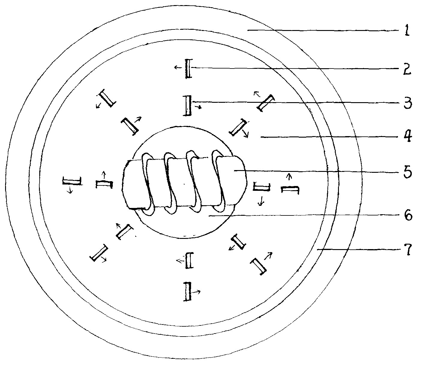
[0007] Example 1: A positive and negative air distribution structure of a biomass burner, including a panel (1), a secondary positive air distribution hole (2), a secondary reverse air distribution hole (3), a combustion chamber (4), and a feed Shaft (5), primary air distribution (6), bellows (7), feed shaft (5) is provided in the middle of the combustion chamber (4), and upper and lower distribution The air holes are respectively the secondary positive distribution air hole (2) layer and the secondary reverse distribution air hole (3) layer. The branch of the secondary positive distribution air hole (2) forms an off-angle with the cut surface of the combustion chamber (4), The deflection angles of the branches of the air distribution holes on the same floor are the same, the deflection angles of the branches of the secondary reverse air distribution holes (3) are opposite to those of the secondary positive air distribution holes (2), and the deflections of the branches of the ...

Embodiment 2

[0008] Example 2: A positive and negative air distribution structure of a biomass burner, including a panel (1), a secondary positive air distribution hole (2), a secondary reverse air distribution hole (3), a combustion chamber (4), and a feed Shaft (5), primary air distribution (6), bellows (7), feed shaft (5) is provided in the middle of the combustion chamber (4), and upper and lower distribution The air holes are respectively the secondary positive distribution air hole (2) layer and the secondary reverse distribution air hole (3) layer. The branch of the secondary positive distribution air hole (2) forms an off-angle with the cut surface of the combustion chamber (4), The deflection angles of the branches of the air distribution holes on the same floor are the same, the deflection angles of the branches of the secondary reverse air distribution holes (3) are opposite to those of the secondary positive air distribution holes (2), and the deflections of the branches of the ...

Embodiment 3

[0009] Example 3: A positive and negative air distribution structure of a biomass burner, including a panel (1), a secondary positive air distribution hole (2), a secondary reverse air distribution hole (3), a combustion chamber (4), and a feed Shaft (5), primary air distribution (6), bellows (7), feed shaft (5) is provided in the middle of the combustion chamber (4), and upper and lower distribution The air holes are respectively the secondary positive distribution air hole (2) layer and the secondary reverse distribution air hole (3) layer. The branch of the secondary positive distribution air hole (2) forms an off-angle with the cut surface of the combustion chamber (4), The deflection angles of the branches of the air distribution holes on the same floor are the same, the deflection angles of the branches of the secondary reverse air distribution holes (3) are opposite to those of the secondary positive air distribution holes (2), and the deflections of the branches of the ...


PUM


Abstract

The invention discloses a forward and reverse air distribution structure for a biomass burner, which comprises a panel, secondary forward air distribution holes, secondary reverse air distribution holes, a burning chamber, a feed shaft, primary air distribution and a bellows, wherein the feed shaft is arranged in the middle of the interior of the burning chamber; and an upper layer of air distribution holes and a lower layer of air distribution holes are uniformly formed in the upper side wall of the periphery of the burning chamber, i.e., a layer of secondary forward air distribution holes and a layer of secondary reverse air distribution holes. A bypass of the secondary forward air distribution holes forms a drift angle with the section of the burning chamber; the drift angle of the bypass of air distribution holes in the same layer leans in the same direction; the drift angle of the bypass of the secondary reverse air distribution holes leans in the direction opposite to the leaning direction of the drift angle of the bypass of the secondary forward power distribution holes; the air in the bellows enters the burning chamber from the secondary forward air distribution holes to flow in circulation so as to form the circulation of air distribution of the upper layer or enters the burning chamber from the secondary reverse power distribution holes to flow cyclically to form the circulation of air distribution of the lower layer; and the circulation of air distribution of the lower layer is reverse to the direction of air distribution of the upper layer. The forward and reverse air distribution structure for a biomass burner has the advantages of sufficient combustion, reasonable air distribution and increased thermal utilization rate of fuel.

Description

technical field [0001] The invention relates to an air distribution structure of a biomass burner, in particular to a forward and reverse air distribution structure of a biomass burner. Background technique [0002] At present, most of the air distribution of the biomass burner is from the bottom to the top, and the second direct air distribution from the inside to the outside. However, due to the large consumption of oxygen in the combustion chamber, there is still insufficient air distribution. Insufficient, it is easy to cause problems such as dead angle of air distribution, unreasonable air distribution, and low fuel utilization rate. Contents of the invention [0003] The present invention aims at the problems of the above-mentioned products, and provides a forward and reverse air distribution structure of the biomass burner, which solves the problems of insufficient combustion of combustible volatiles in the above-mentioned products, which may easily cause dead angle...

Claims


Application Information

Patent Timeline
Patent Type & Authority Applications(China)
IPC IPC(8): F23C7/00
Inventor 席礼
Owner SHANXI RONGSHENDA SCI & TECH
Why Eureka
Try Eureka