Al technical title is built by PatSnap Al team. It summarizes the technical point description of the patent document.
A technology of fiber coupling device and fiber laser, which is applied in the field of lasers and can solve the problems of difficult cooling of optical fiber and inability to maintain the stability of optical fiber position for a long time.
Inactive Publication Date: 2012-11-28
BEIJING GK LASER TECH
View PDF7 Cites 12 Cited by
Summary
Abstract
Description
Claims
Application Information
AI Technical Summary
This helps you quickly interpret patents by identifying the three key elements:
Problems solved by technology
Method used
Benefits of technology
Problems solved by technology
[0003] The traditional optical fiber coupling device is generally an optical adjustment frame, which can realize five-dimensional adjustment of optical fibers, but its disadvantage is that there are elastic elements such as springs on the adjustment frame, which cannot maintain the stability of the optical fiber position for a long time, and this structure is not easy to cool the optical fiber.
Method used
Image
Click on the blue label to locate the original text in one second.
Reading with bidirectional positioning of images and text.
Examples
Embodiment Construction
[0077] In order to make the object, technical solution and advantages of the present invention clearer, the present invention will be further described in detail below in conjunction with the accompanying drawings. It should be understood that the specific embodiments described here are only used to explain the present invention, not to limit the present invention.
[0078] The inventors have found through research that by replacing the elastic element with a mechanical hard connection in the device, the mutual position between the end face of the optical fiber and the focal point can be guaranteed, and the positional stability of the end face of the optical fiber and the focal point can be ensured.
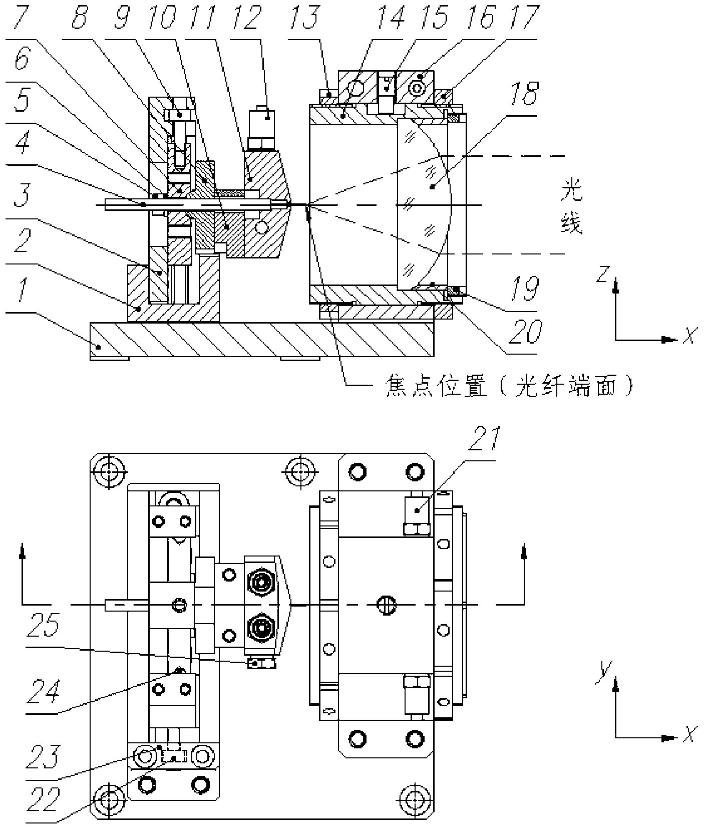
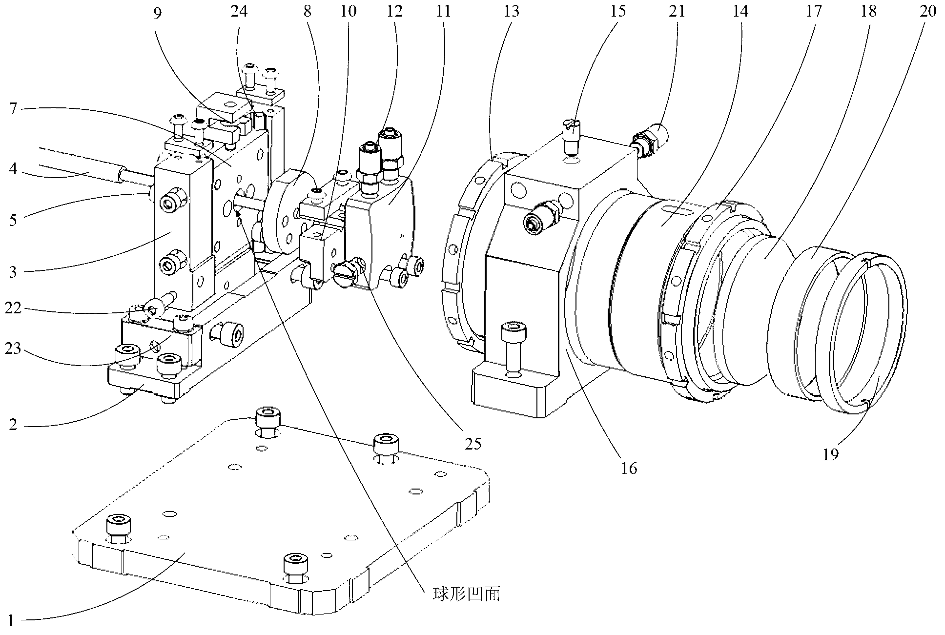
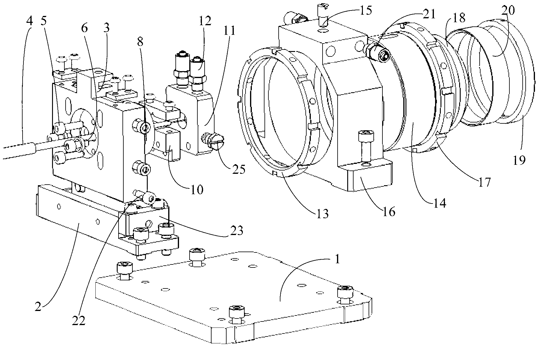
[0079] According to an embodiment of the present invention, a fiber coupling device for a fiber laser is provided, including: a bottom plate assembly, a fiber support assembly, and a focusing lens barrel assembly.
[0080] refer to figure 1 and Figure 2 (including Figure 2a an...
PUM
Abstract
The invention provides an optical fiber coupling device of a fiber laser comprises bottom plate, an optical fiber support base, an optical fiber support lateral moving plate, an angle adjustment screw, a spherical washer, an optical fiber support longitudinal moving plate, an optical fiber support angle adjustment plate, a longitudinal adjustment screw, an optical fiber fixed seat, an optical fiber water-cooling block, an optical fiber water-cooling block water nozzle, a rear end locking nut of a focusing lens barrel, the focusing lens barrel, a guide pin of the focusing lens barrel, a focusing lens barrel seat, a front end locking nut of the focusing lens barrel, a focus lens, a focus lens pressing ring, a focus lens washer, a focusing lens barrel seat water nozzle, a transverse adjustment screw, a limit block of the transverse adjustment screw, a guide rod and an optical fiber water-cooling screw plug. The optical fiber support lateral moving plate is matched with the U-shaped structure of the optical fiber support base, the optical fiber support longitudinal moving plate is matched with the U-shaped structure of optical fiber support lateral moving plate, the optical fiber support angle adjustment plate is matched with the optical fiber support longitudinal moving plate through a spherical surface, and the excircle of the focusing lens barrel is matched with the bore of the focusing lens barrel seat. The optical fiber coupling device has a compact structure, is convenient to operate, and is stable and reliable.
Description
technical field [0001] The invention relates to the field of lasers, in particular to a fiber coupling device for a fiber laser. Background technique [0002] As a representative of the third-generation laser technology, fiber lasers are being used more and more widely. The fiber coupling device is an important part of the fiber laser, which directly affects the coupling efficiency and even affects the power index of the laser. [0003] The traditional optical fiber coupling device is generally an optical adjustment frame, which can realize five-dimensional adjustment of optical fibers, but its disadvantage is that there are elastic elements such as springs on the adjustment frame, which cannot maintain the stability of the optical fiber position for a long time, and this structure is not easy to cool the optical fiber. . Contents of the invention [0004] The technical problem to be solved by the present invention is to provide a fiber laser fiber coupling device, which...
Claims
Application Information
Patent Timeline
Application Date:The date an application was filed.
Publication Date:The date a patent or application was officially published.
First Publication Date:The earliest publication date of a patent with the same application number.
Issue Date:Publication date of the patent grant document.
PCT Entry Date:The Entry date of PCT National Phase.
Estimated Expiry Date:The statutory expiry date of a patent right according to the Patent Law, and it is the longest term of protection that the patent right can achieve without the termination of the patent right due to other reasons(Term extension factor has been taken into account ).
Invalid Date:Actual expiry date is based on effective date or publication date of legal transaction data of invalid patent.