
Permanent-magnet rapid operation mechanism

A fast-operating, permanent-magnet technology, applied in the direction of the power device inside the switch, can solve the problems such as the inability to obtain the rigid speed, limit the bistable permanent magnet operating mechanism, etc., achieve simple structure, convenient installation and debugging, and improve electrical life. Effect

Active Publication Date: 2012-11-28
中国船舶重工集团公司第七一二研究所
View PDF4 Cites 14 Cited by
  • Summary
  • Abstract
  • Description
  • Claims
  • Application Information

AI Technical Summary

Problems solved by technology

By comparing the working principles and structures of the two permanent magnet operating mechanisms, it can be seen that the output characteristics of the bistable permanent magnet operating mechanism are inconsistent with the load characteristics of the circuit breaker, thus limiting the application of the bistable permanent magnet operating mechanism; The output characteristics of the state permanent magnet operating mechanism have the advantages of the spring operating mechanism, which can be well matched with the load characteristics of the circuit breaker. However, the development of this type of operating mechanism to high-power circuit breakers is limited due to the inability to obtain the ideal rigid-point speed. application

Method used


Image

  • Permanent-magnet rapid operation mechanism
  • Permanent-magnet rapid operation mechanism

Examples


Embodiment Construction

[0023] The present invention is further described as follows in conjunction with accompanying drawing and embodiment:

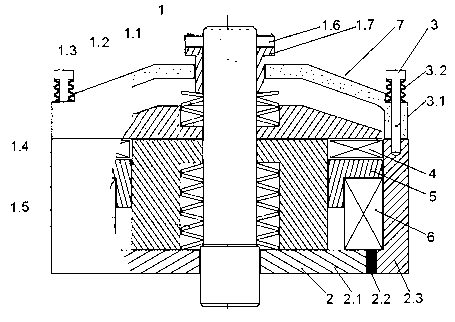
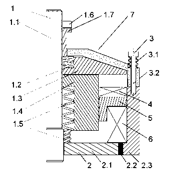
[0024] Such as figure 1 , 2 Shown: a permanent magnet quick operating mechanism, including a moving iron core assembly 1, a static iron core assembly 2, an opening coil 4, a flange 5, a closing coil 6, a cover plate 7 and a buffer assembly 3; The iron core assembly 1 is composed of a guide rod 1.1 and several components sleeved on the guide rod 1.1. The components are: moving iron core spring 1.5, moving iron core 1.4, repulsion disk 1.3, repulsion disk spring 1.2, adjustment nut 1.7 and lock nut 1.6; the static iron core assembly 2 includes a bottom plate 2.1 that is sleeved on the guide rod 1.1 and is in contact with the moving iron core spring 1.5, the bottom plate 2.1 is covered with a permanent magnet 2.2, and the permanent magnet 2.2 is covered There is a sleeve 2.3; there is a flange 5 in the cavity between the inner peripheral surface of the sleeve ...


PUM


Abstract

The invention relates to a permanent-magnet rapid operation mechanism, which comprises a movable iron-core component, a static iron-core component, an opening coil, a flange, a closing coil, a cover plate and a buffering component, wherein the movable iron-core component comprises a guide rod and a plurality of members sleeving the guide rod; the static iron-core component comprises a bottom plate sleeving the guide rod and contacted with the movable iron-core spring; the bottom plate is sleeved with a permanent magnet; the permanent magnet is sleeved with a sleeve; on the side of the flange facing the permanent body is sleeved with the closing coil; the opening coil sleeving the movable iron core is positioned on the side of the flange facing a repulsion plate; and the cover plate sleeving an adjusting nut is connected with an end surface of a sleeve through the buffering component. The permanent-magnet rapid operation mechanism has the following advantages: 1, the opening operation can be carried out in a common speed opening mode and a failure rapid opening mode as required; 2, the permanent-magnet rapid operation mechanism has the characteristics of closing maintenance of a permanent magnet mechanism and rapid opening of a repulsion plate mechanism; and 3, the structure is simple, and the installation and the debugging are convenient.

Description

technical field [0001] The invention relates to a permanent magnet fast operating mechanism, in particular to a permanent magnet mechanism capable of permanent magnet closing and fast opening. Background technique [0002] The existing permanent magnet operating mechanism at home and abroad can be divided into two types according to its working principle and structure: monostable permanent magnet operating mechanism and bistable permanent magnet operating mechanism. Among them, the working principle of the bistable permanent magnet operating mechanism is that the opening and closing positions are maintained by permanent magnetic attraction; the working principle of the monostable permanent magnet operating mechanism is that the opening is based on the opening spring and the contact spring of the interrupter. Open under the action of the switch, and keep it in the open position, only the closed position is maintained by the permanent magnetic attraction. By comparing the wor...

Claims


Application Information

Patent Timeline
IPC IPC(8): H01H3/28
Inventor 马子文赵成宏肖文华章程杨晨光
Owner 中国船舶重工集团公司第七一二研究所
Learn More