
Electromechanical transient model for cascade connection type multi-terminal direct current power transmission system and inter-station coordination method

A multi-terminal DC and transient model technology, applied in the direction of DC network circuit devices, electrical components, circuit devices, etc., can solve the problem of ancient control methods, no consideration of coordinated control strategies among multiple converter stations, and large differences in control characteristics. And other issues

Active Publication Date: 2014-07-23
CHINA ELECTRIC POWER RES INST +1
View PDF3 Cites 0 Cited by
  • Summary
  • Abstract
  • Description
  • Claims
  • Application Information

AI Technical Summary

Problems solved by technology

[0003] (1) The inverter part does not simulate the process of commutation failure, which is quite different from the actual response of the inverter;
[0004] (2) The control method is ancient, which is quite different from the control characteristics of modern direct current transmission projects;
[0005] (3) Inter-station coordination control strategy without consideration of multiple converter stations
[0006] (4) This model is a parallel multi-terminal direct current transmission system model, not a cascaded multi-terminal direct current transmission system model, which cannot meet the needs of cascaded multi-terminal direct current transmission system simulation
However, there is not yet a complete set of schemes for inter-station voltage and current coordination of cascaded multi-terminal direct current transmission systems, such as how to coordinate and control systems with different topologies, etc.

Method used


Image

  • Electromechanical transient model for cascade connection type multi-terminal direct current power transmission system and inter-station coordination method
  • Electromechanical transient model for cascade connection type multi-terminal direct current power transmission system and inter-station coordination method
  • Electromechanical transient model for cascade connection type multi-terminal direct current power transmission system and inter-station coordination method

Examples


Embodiment

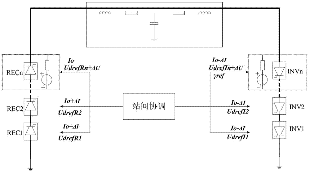
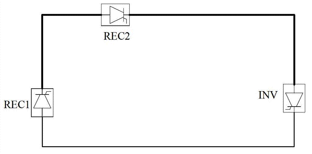
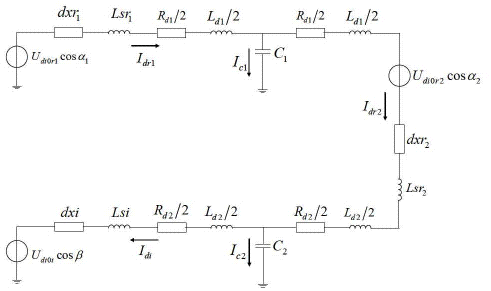
[0064] Taking the ±800kV cascaded multi-terminal DC transmission system as an example, it is designed to place two 12-pulse converters in the single pole of the UHV DC transmission system at different geographical locations, and connect them with DC lines to realize multi-power supply. Power supply and multi-drop power reception. Specifically, there are three main wiring modes of the ±800kV cascaded multi-terminal DC transmission system: three-terminal and four-terminal. Type I has two rectifier stations and one inverter station, such as figure 2 Shown; Type II has one rectifier station and two inverter stations, such as Figure 4 Shown; Type III has two rectifier stations and two inverter stations, such as Figure 6 shown. The DC circuit model of each wiring mode corresponds to image 3 , 5, 7.

[0065] Among them, according to the quasi-steady-state equation, the converter is equivalent to the Thevenin circuit with the series impedance of the voltage source, and the DC...


PUM


Abstract

The invention relates to an electromechanical transient model for a cascade connection type multi-terminal direct current power transmission system and an inter-station coordination method. According to the method, the model is based on the existing two-terminal direct current electromechanical transient model, the direct current side circuit is extended to a cascade connection multi-terminal structure, a complete direct current side circuit is established, the two-terminal direct current margin coordination strategy is extended to a cascade connection multi-terminal system, and an inter-station coordination control method in the cascade connection system is provided; and moreover, according to the electromechanical transient model and the method, the three-terminal and four-terminal + / -800kV cascade connection extra-high voltage direct current power transmission system is covered.

Description

technical field [0001] The invention relates to the technical field of power system simulation and modeling, in particular to an inter-station coordination method for an electromechanical transient model of a cascaded multi-terminal direct current transmission system. Background technique [0002] At present, the conventional two-terminal HVDC transmission project is widely used, and the simulation calculation model tends to be mature. Compared with the two-terminal DC transmission system, the modeling of the multi-terminal DC transmission system is relatively lagging behind. In China, the multi-terminal DC transmission model in the electromechanical transient simulation software PSD-BPA is mainly used. The main disadvantages of this model are: [0003] (1) The inverter part does not simulate the process of commutation failure, which is quite different from the actual response of the inverter; [0004] (2) The control method is ancient, which is quite different from the co...

Claims


Application Information

Patent Timeline
Patent Type & Authority Patents(China)
IPC IPC(8): H02J1/00
Inventor 万磊
Owner CHINA ELECTRIC POWER RES INST
Learn More