Bi-directionally magnetically coupled and axially excited and limited rotating-shaft piezoelectric generator

An axial and piezoelectric technology, applied in the direction of generators/motors, piezoelectric effect/electrostrictive or magnetostrictive motors, electrical components, etc., can solve low reliability, piezoelectric vibrator fragmentation, discomfort, etc. problems, to achieve the effect of high reliability, no contact impact and noise, and strong speed adaptability

Inactive Publication Date: 2012-11-28
ZHEJIANG NORMAL UNIVERSITY
View PDF5 Cites 38 Cited by
  • Summary
  • Abstract
  • Description
  • Claims
  • Application Information

AI Technical Summary

Problems solved by technology

[0004] The common feature of the above three types of rotating shaft piezoelectric generators that rotate with the rotating body is that the piezoelectric vibrator deforms along the rotating direction of the rotating body, and the amount of deformation and power generation depends entirely on the rotating speed and rotation state of the rotating body. The disadvantages are: ①The deformation of the piezoelectric vibrator is uncontrollable, and excessive deformation will cause the

Method used


Image

  • Bi-directionally magnetically coupled and axially excited and limited rotating-shaft piezoelectric generator
  • Bi-directionally magnetically coupled and axially excited and limited rotating-shaft piezoelectric generator
  • Bi-directionally magnetically coupled and axially excited and limited rotating-shaft piezoelectric generator

Examples


Embodiment approach

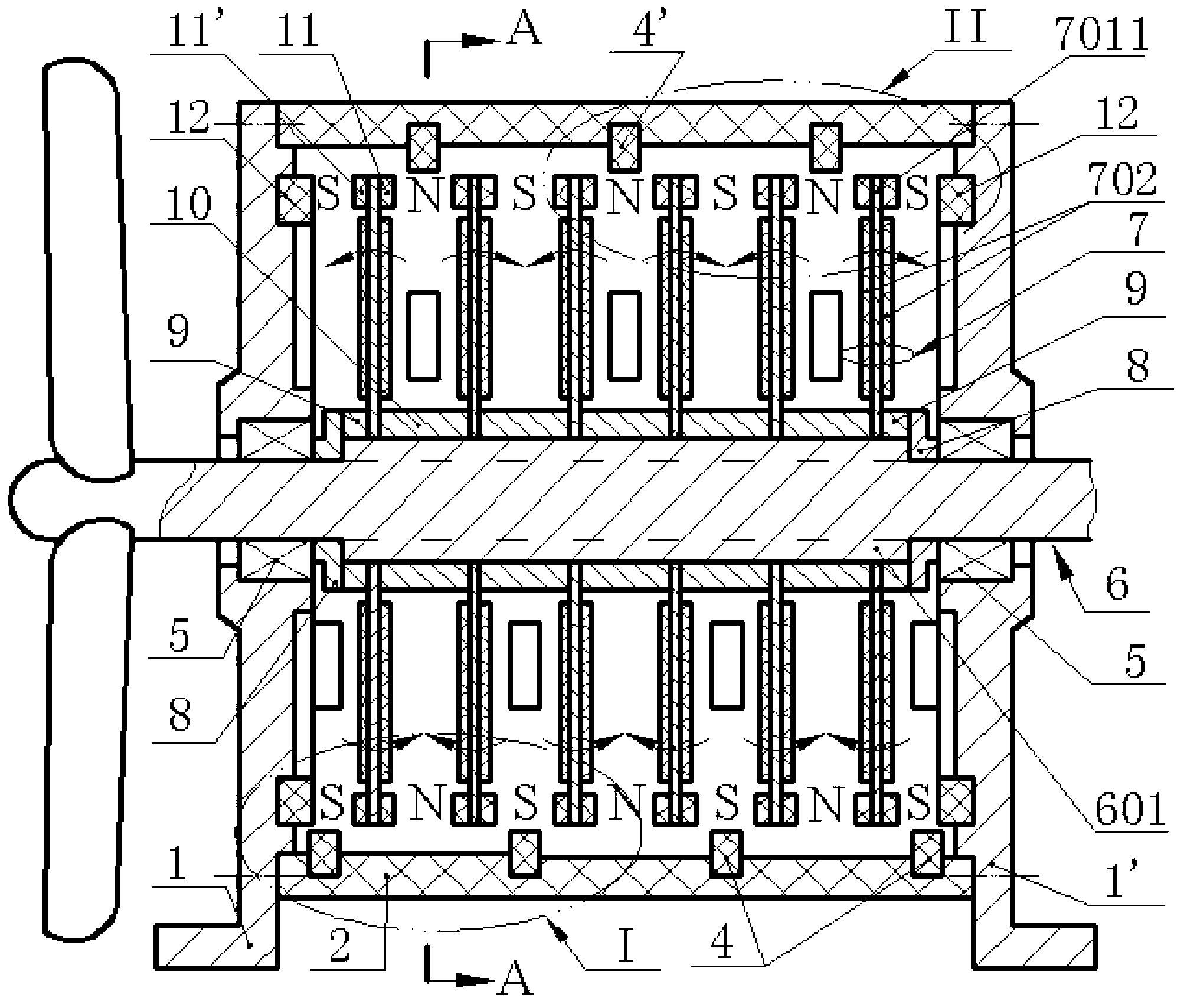
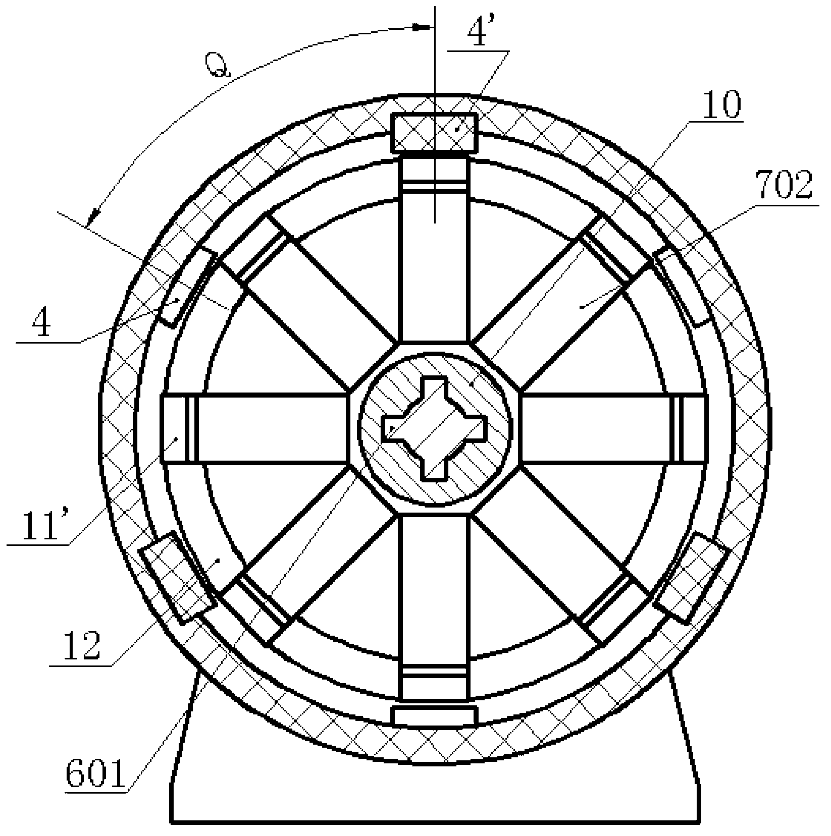
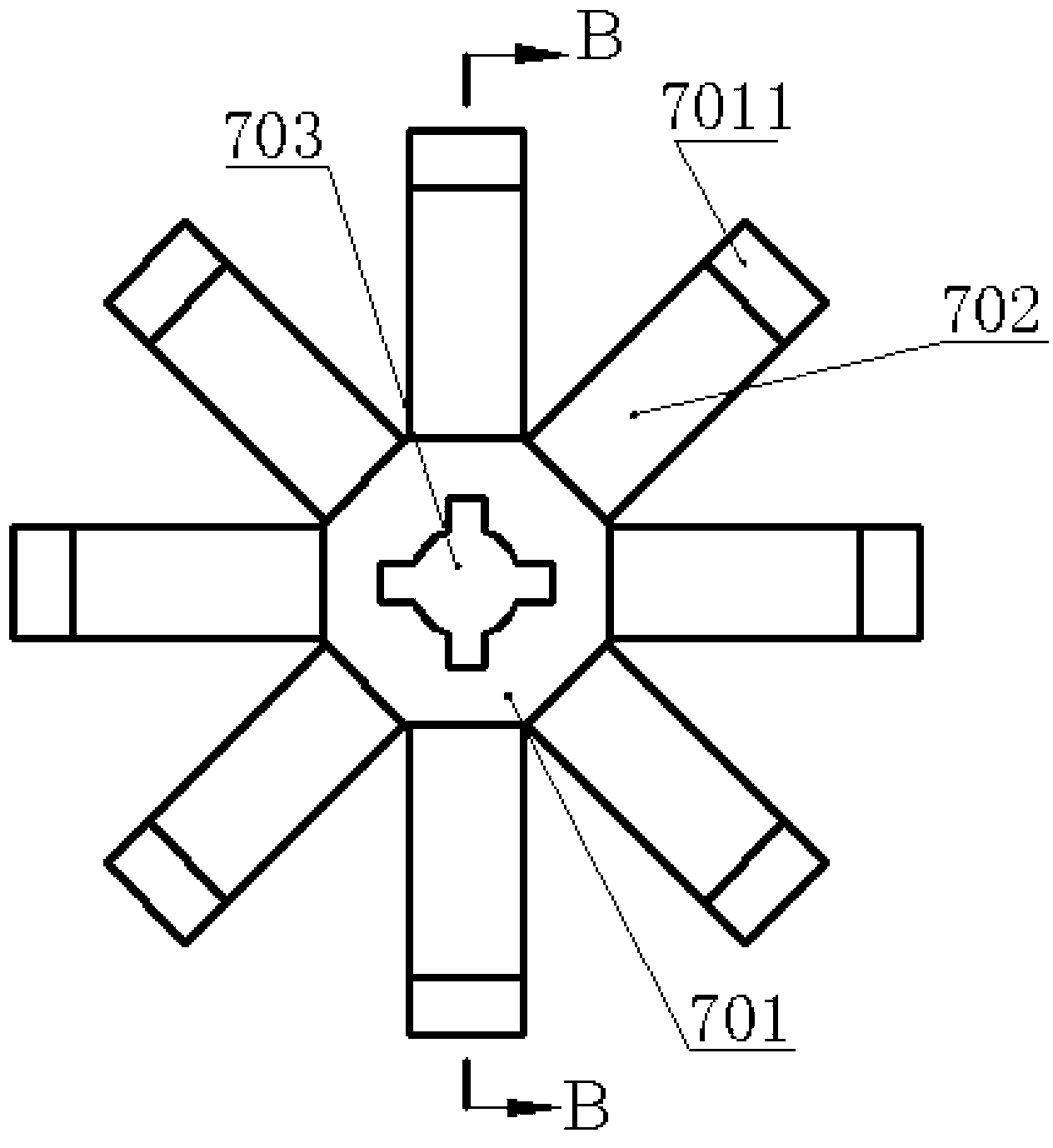
[0018] The cylinder 2 is fixedly connected by screws between the two bearing seats 1 and 2 1', and multiple sets of fixed magnets 4 and 2 4' are alternately inlaid on different cross-sections of the inner wall of the cylinder 2. The magnetic poles of the first fixed magnet 4 and the second fixed magnet 4' are installed along the radial direction of the cylinder 2, and the directions of the magnetic poles are opposite; 5 and magnetic ring 12, and the magnetic ring 12 on the bearing seat 1 and bearing seat 2 1' points to the magnetic pole polarity in the cylinder 2 and the adjacent moving magnet 4 or moving magnet 2 4' points to the circle The magnetic poles in the cylinder 2 have the same polarity; the main shaft 6 is installed on the two bearing seats 1 and 1' through the two bearings 5, and the spline 601 of the main shaft 6 is covered with a piezoelectric transducer device 7, each group of piezoelectric transducers 7 is crimped between the two bearings 5 ​​by a pair of stepp...


PUM


Abstract

The invention relates to a bi-directionally magnetically coupled and axially excited and limited rotating-shaft piezoelectric generator and belongs to the field of piezoelectric generation. A cylinder is fixed between two bearing blocks by a bolt; multiple groups of static magnets I and static magnets II are alternately embedded on different cross sections of the internal wall of the cylinder; both the two bearing blocks are embedded with a bearing and a magnetic ring; a main shaft is arranged on the bearing block by the bearing; the spline of the main shaft is sleeved with multiple groups of piezoelectric transducers; and a pair of moving magnets are arranged at the free end of each of the piezoelectric transducers by bolts, and the opposite magnetic poles of the moving magnets are opposite. The piezoelectric generator has the advantages of no contact impact and noise, high reliability, convenience for providing electricity to a monitoring system rotating along with a rotating shaft, and capability of generating power at a constant or high speed.

Description

technical field [0001] The invention belongs to the field of piezoelectric power generation, and in particular relates to a shaft-type piezoelectric generator with two-way magnetic coupling axial excitation and position limitation, which is used for power supply of a rotating machinery health monitoring system. Background technique [0002] The research on constructing micro-scale piezoelectric generators by using sheet-type piezoelectric vibrators has become a hot spot both at home and abroad for many years. According to the different sources of motive power and application purposes of generators, cantilever beam piezoelectric generators with various structural forms have been proposed at home and abroad, mainly including vibration type and rotary type. Among them, the rotary piezoelectric generator was originally proposed to solve the self-powered sensor monitoring of rotating machinery such as helicopter propellers, automobile tire pressure, aeroengines / high-speed trains / ...

Claims


Application Information

Patent Timeline
IPC IPC(8): H02N2/18
Inventor 王淑云阚君武徐海龙蔡建成尹晓红曾平
Owner ZHEJIANG NORMAL UNIVERSITY
Why Eureka
Try Eureka