
Vacuum cleaner filter bag having a side fold

A technology of vacuum cleaners and filter bags, which can be used in cleaning equipment, cleaning devices, specific bag/box production, etc., and can solve the problems of complex non-woven square bottom bag production

Active Publication Date: 2012-11-28
EUROLIFTERS HLDG NV
View PDF23 Cites 0 Cited by
  • Summary
  • Abstract
  • Description
  • Claims
  • Application Information

AI Technical Summary

Problems solved by technology

The manufacture of non-woven square bottom bags is more complicated

Method used


Image

  • Vacuum cleaner filter bag having a side fold
  • Vacuum cleaner filter bag having a side fold
  • Vacuum cleaner filter bag having a side fold

Examples


Embodiment Construction

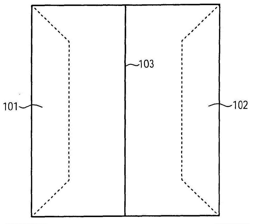
[0068] figure 1 A plan view of an exemplary vacuum cleaner filter bag is schematically shown. The exemplary vacuum cleaner filter bag has a rectangular design and comprises two side folds 101 and 102 each formed by two folded legs. The two side folds are shown here in the folded-in or folded-in state. In this state, the vacuum cleaner filter bag can easily be inserted into the vacuum cleaner. Additionally, this condition allows for a small package size and allows for easy deployment of the vacuum cleaner filter bag while the vacuum cleaner is in operation.

[0069] When inserting the vacuum cleaner filter bag into the vacuum cleaner and exposing the vacuum cleaner filter bag to the air flow to be cleaned in the vacuum cleaner, it is possible in particular to pass through the vacuum cleaner filter bag in the vacuum cleaner housing. The pressure difference between the inside and outside causes the side folded parts 101 and 102 to turn to the outside accordingly, thereby incre...


PUM


Abstract

The invention comprises a vacuum cleaner filter bag having at least one side fold formed by two fold legs, wherein the vacuum cleaner filter bag is designed as a tubular bag, wherein, in a turned-in state, the at least one side fold has at least three edges, wherein two of the edges are formed by a respective weld seam, and wherein the side fold can be turned out by the edges formed by a weld seam.

Description

technical field [0001] The invention relates to a vacuum cleaner filter bag having at least one side fold formed by two folded legs. Background technique [0002] Vacuum cleaner filter bags are usually made of non-woven fabric. Due to the excellent dust storage capacity of vacuum cleaner filter bags made of non-woven fabrics, such vacuum cleaner filter bags have practically replaced paper filter bags. The manufacture of non-woven bags is fundamentally different from the manufacture of paper bags. Currently, rectangular flat bags formed from upper and lower layers and welded circumferentially at the borders are common. Such filter bags are known, for example, from EP 0 161 790 , EP 0 639 061 , EP 1 059 056 or EP 1 661 500 . [0003] In order to achieve a greater filling volume, flat bags are used which have a surrounding weld seam and side folds which can be turned outwards, compared to completely flat bags which simultaneously have a small pack size. . Such a filter bag...

Claims


Application Information

Patent Timeline
Patent Type & Authority Applications(China)
IPC IPC(8): A47L9/14B31B41/00
CPCB31B2241/008B31B2237/40B31B41/00B31B2219/148B31B2219/2681A47L9/14B31B70/148B31B70/262B31B2155/001Y10T156/1007Y10T156/1008Y10T156/101Y10T156/1011Y10T156/1013Y10S55/02Y10S55/05B31B2160/20Y10S15/08
Inventor 拉尔夫·赛耶简·舒尔廷克
Owner EUROLIFTERS HLDG NV
Learn More