Calibration of a base coordinate system for an industrial robot

A technology of industrial robots and robots, applied in the directions of instruments, manipulators, manufacturing tools, etc., can solve the problems of inaccuracy, difficulty in adjustment, and inaccessibility, and achieve the effect of fast, easy-to-use, and easy-to-use calibration methods.

Inactive Publication Date: 2012-11-28
ABB RES LTD
View PDF7 Cites 9 Cited by
  • Summary
  • Abstract
  • Description
  • Claims
  • Application Information

AI Technical Summary

Problems solved by technology

The problem with moving the robot between different work areas is that the position and orientation of the robot relative to the work area must be determined with high precision each time the robot is moved into the work area
This method is difficult to use for the calibration of the base coordinate system of a robot on a movable platform for the following reasons: When the robot has assumed a new pose, it is difficult to adjust the robot calibration procedure to fit the spherical piece with the three targets because they are scattered In the robot cell; after the robot has moved, there is a great risk that the robot will not be able to touch all three objects; since considerable distances are required between the objects, the inaccuracy of the robot will always reduce the quality of the calibration; The robot tool can have any orientation for each mate, which further reduces the accuracy of the method when used for calibration of the base coordinate system; guidance is the most intuitive method, and with mate via guidance, it is difficult or sometimes impossible to The spherical piece moves to three targets

Method used


Image

  • Calibration of a base coordinate system for an industrial robot
  • Calibration of a base coordinate system for an industrial robot
  • Calibration of a base coordinate system for an industrial robot

Examples


Embodiment Construction

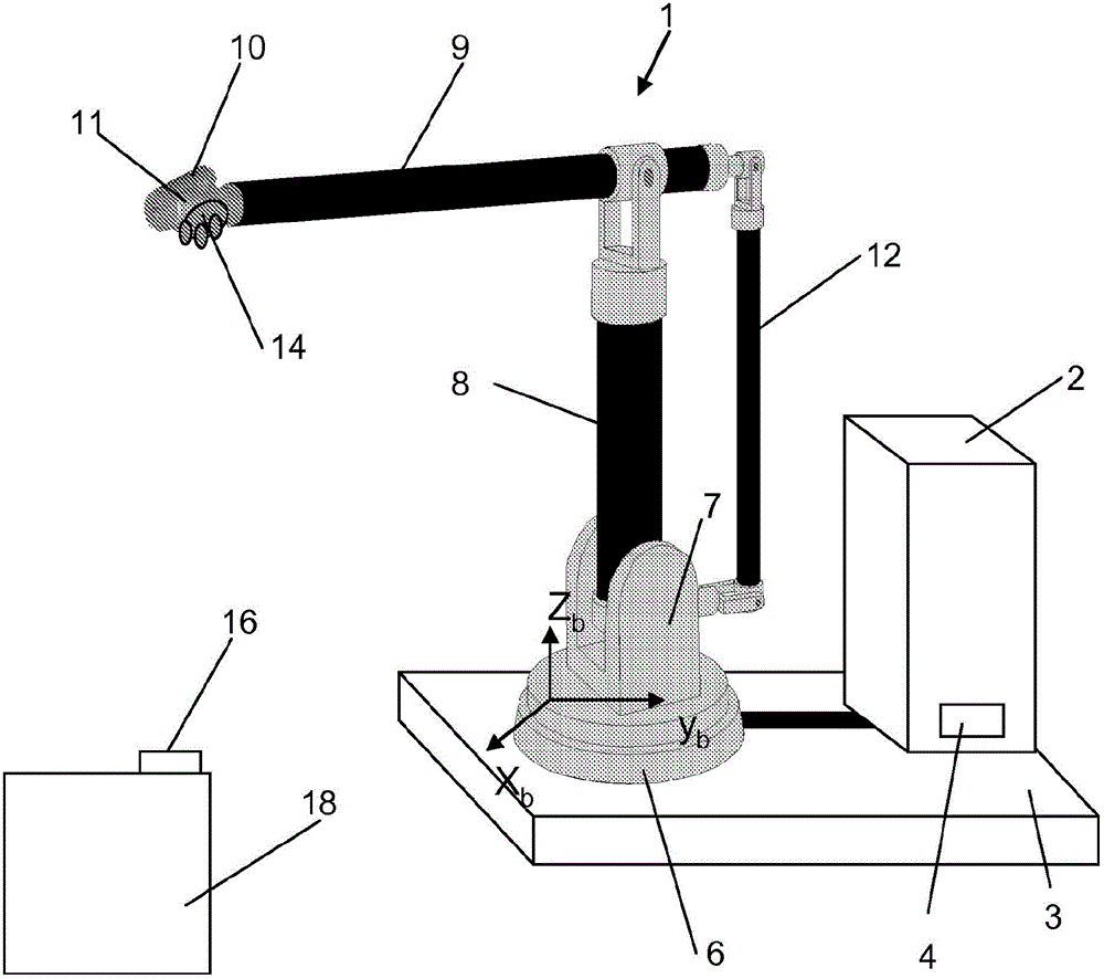
[0037] figure 1 An example of a portable robot is given in which a lightweight robot 1 including a robot controller 2 is mounted on a movable platform 3 . The portable robot is positioned in a robot cell that defines the robot's work area. The robot controller 2 is also mounted on the platform, but there are cases when each robot cell can have its own controller, then only the robot will be on the platform. The robot 1 is connected to the controller 2 through a cable, and when docking, the robot, tool and controller are electrically connected to the unit using contacts 4 . The robot comprises a fixed base part 6 bearing a stand 7 rotatable about a first axis. This bracket 7 supports a lower arm 8 which is rotatable about a second axis. The lower arm 8 supports an upper arm 9 rotatable about a third axis. The upper arm 9 supports a wrist 10 rotatable about fourth, fifth and sixth axes. The wrist 10 supports a wrist interface 11 , hereinafter referred to as a wrist flange, ...


PUM


Abstract

The present invention relates to a method for calibration of a base coordinate system of an industrial robot (1 ) in relation to a work area, the robot having a base portion (6) and a robot wrist interface movable in at least four degrees of freedom with respect to the base portion. The method comprises: - mounting a first part (14) of a kinematic coupling which is constrained in the same number of degrees of freedom as the robot, on the robot wrist interface (11 ) of the robot, - mounting a second part (16) of the kinematic coupling in the work area, - moving the robot including the base portion to the work area, - setting the robot in compliant control mode, - moving the first part of the kinematic coupling to mate with the second part, - storing axis positions of the robot during mating of the kinematic coupling, - determining the position and orientation of the base portion based on the stored axis positions and a kinematic model of the robot, and on basis thereon calibrating the base coordinate system of the robot.

Description

technical field [0001] The invention relates to a method for calibrating a base coordinate system of a robot with respect to a working area. [0002] The invention also relates to a kinematic coupling for calibration of a base coordinate system of a robot. Background technique [0003] The invention is particularly useful for calibration of portable robots. Wherein, a portable robot refers to a robot that can move by itself or through other devices such as a steering trolley. A work area is where a robot performs work, for example a robot cell. For example, a work area includes work objects and / or workstations on which a robot performs work. [0004] The robot includes a base part and a plurality of parts movable relative to the base part. A base coordinate system is defined in a fixed relationship to the base portion. During calibration of the base coordinate system, the position and orientation of the base coordinate system and the corresponding position and orientati...

Claims


Application Information

Patent Timeline
Patent Type & Authority Applications(China)
IPC IPC(8): B25J9/16
CPCB25J9/1692G05B2219/39027G05B2219/39032
Inventor 托里尼·布罗加德
Owner ABB RES LTD
Why Eureka
Try Eureka