
Multi-stage turbocharger arrangement

A turbocharger and supercharger technology, applied in the direction of machines/engines, gas turbine devices, high-efficiency propulsion technology, etc., can solve problems such as high production costs, insufficient heat dissipation or cooling, and increased weight, and achieve cheap Effect of production and machining, heat reduction

Inactive Publication Date: 2012-11-28
BORGWARNER INC
View PDF8 Cites 3 Cited by
  • Summary
  • Abstract
  • Description
  • Claims
  • Application Information

AI Technical Summary

Problems solved by technology

This design requires a large construction volume and increased weight and leads to high production costs for a multi-stage turbocharger arrangement of this type
Furthermore, prior art multi-stage turbocharger arrangements have insufficient heat dissipation or cooling due to the high thermodynamically efficient structural mass and the large internal surface area of ​​the exhaust gas flow ducts
As a result, thermal stresses due to high temperature differences between the individual components can be avoided only to an undue degree, which adversely affects the operating life of the individual components

Method used


Image

  • Multi-stage turbocharger arrangement
  • Multi-stage turbocharger arrangement

Examples


Embodiment Construction

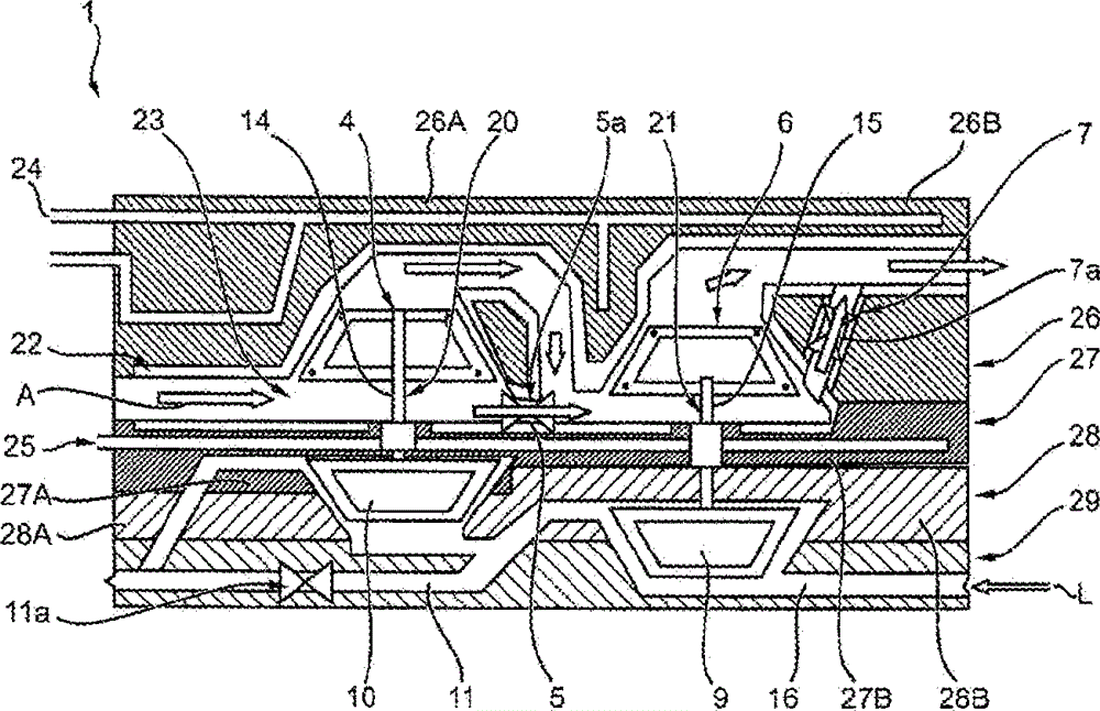
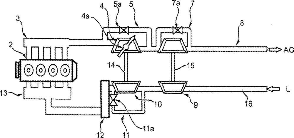
[0038] see figure 1 , an embodiment of the multi-stage turbocharger arrangement 1 according to the invention will be described below. as from figure 1 As can be seen in the figure, the multi-stage turbocharger arrangement 1 has a high-pressure turbocharger 20 and a low-pressure turbocharger 21, the high-pressure turbocharger having a shaft 14 connected to a high-pressure compressor 10 and the low-pressure turbocharger has a low-pressure turbine 6 connected via a shaft 15 to a low-pressure compressor 9 . The high-pressure turbine 4 and the low-pressure turbine 6 are arranged in a common turbine housing unit 26, which is divided into a turbine housing part 26A of the high-pressure turbocharger 20 and the low-pressure turbocharger. A turbine housing portion 26B of the machine 21. An inner casing 23 , which can expand due to heat, is inserted into the interior of the turbine housing unit 26 , in which hot engine exhaust gas Ag flows through the high-pressure turbine 4 and the l...


PUM


Abstract

The present invention relates to a multi-stage turbocharger arrangement (1), having a high-pressure turbocharger (20) which has a turbine housing (26A), a bearing housing (27A), a compressor housing (28A); and having a low-pressure turbocharger (21) which has a turbine housing (26B), a bearing housing (27B), a compressor housing (28B); wherein the turbine housings (26A, 26B) are combined to form at least one turbine housing unit (26), and / or wherein the bearing housings (27A, 27B) are combined to form at least one bearing housing unit (27), and / or wherein the compressor housings (28A, 28B) are combined to form at least one compressor housing unit (28).

Description

technical field [0001] The invention relates to a multi-stage turbocharger arrangement for an internal combustion engine according to the preamble of claim 1 . Background technique [0002] Conventional multi-stage turbocharger arrangements known from the prior art generally consist of at least two turbochargers arranged in series, and the compressor housing, bearing housing and turbine housing of the turbochargers are connected to each other by a plurality of flanges or other connecting elements. This design requires a large structural volume and increased weight and leads to high production costs for a multi-stage turbocharger arrangement of this type. Furthermore, prior art multi-stage turbocharger arrangements have insufficient heat dissipation or cooling due to the high thermodynamically effective structural mass and the large internal surface area of ​​the exhaust gas flow duct. As a result, thermal stresses due to high temperature differences between the individual ...

Claims


Application Information

Patent Timeline
IPC IPC(8): F02B37/013F02B39/00F02B37/18F02B37/12
CPCF05D2230/53F02B37/013F02B37/127F02C6/12F01D9/026F02B37/18F05D2230/50Y02T10/144F02B37/004F05B2230/50F01D17/105F01D25/125F01D25/24F02B39/005F05D2240/40F02B37/162Y02T10/12Y02T50/60F02B37/12F02B39/00
Inventor V·乔格T·齐纳尔W·文策尔T·克瑞汀格
Owner BORGWARNER INC
Learn More