
Twin-clutch transmission and bearing system for the input shafts of a twin-clutch transmission

A supporting device and driving shaft technology, applied in the direction of transmission, gear transmission, multi-ratio transmission, etc., can solve the problems of large structural space, unfavorable length, unsuitable for horizontal installation, etc., to save processing costs and save structure effect of space

Inactive Publication Date: 2009-07-01
VOLKSWAGEN AG
View PDF9 Cites 0 Cited by
  • Summary
  • Abstract
  • Description
  • Claims
  • Application Information

AI Technical Summary

Problems solved by technology

Disadvantageously, with a fixed bearing designed as a double row angular contact ball bearing via which the drive shaft is fixedly mounted, this known mounting requires a relatively large construction space, especially in the axial direction, that is, The transmission associated therewith has an unfavorable length due to this bearing arrangement and is therefore not suitable for the transverse installation of the drive unit consisting of the drive motor and the transmission

Method used


Image

  • Twin-clutch transmission and bearing system for the input shafts of a twin-clutch transmission

Examples


Embodiment Construction

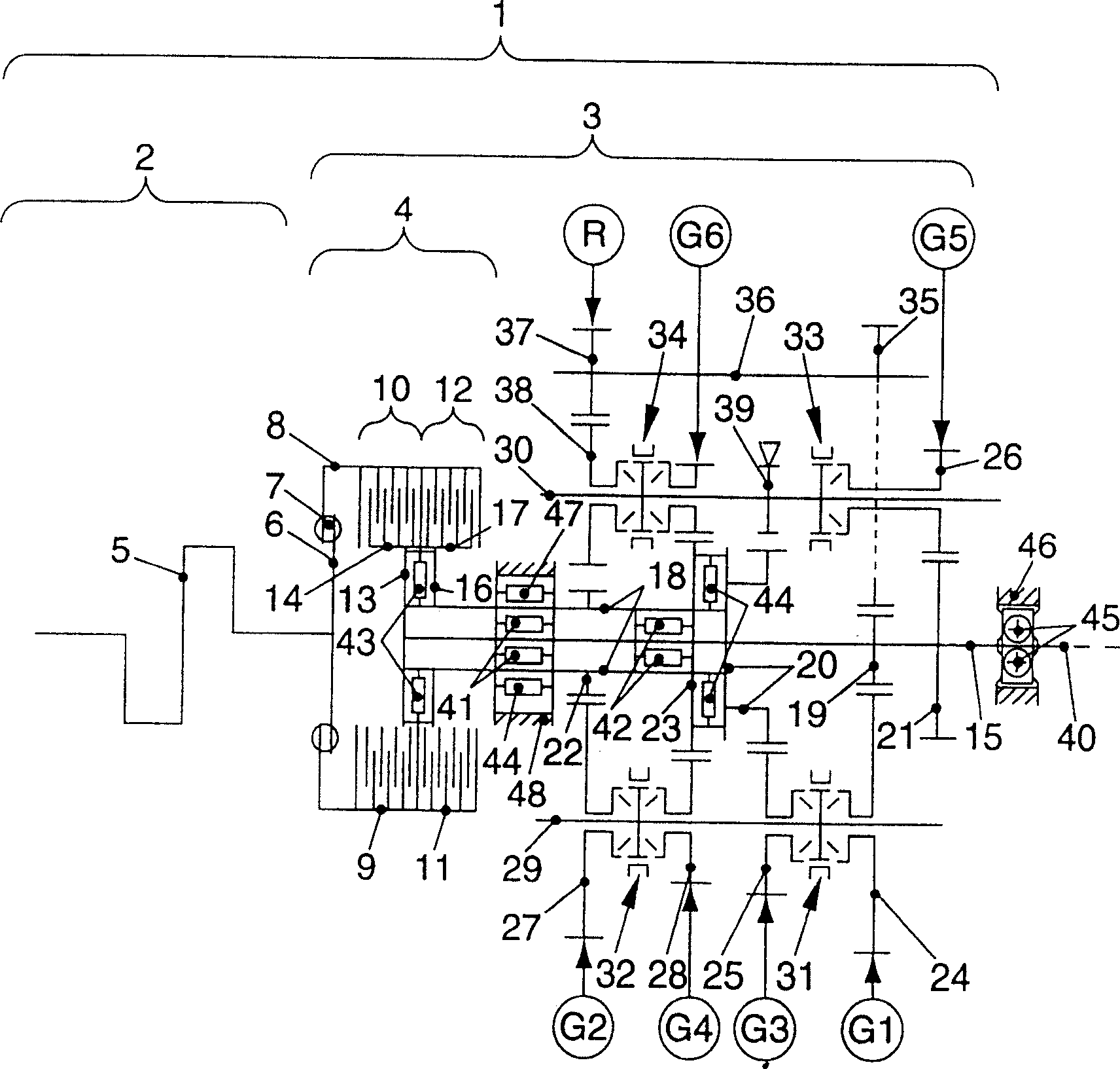
[0012] exist figure 1A drive unit 1 of a motor vehicle is shown in , which consists of a drive motor 2 and a multi-clutch transmission 3 with an associated clutch unit 4 . Drive engine 2 is an internal combustion engine, represented by a crankshaft 5 . The crankshaft 5 is connected to a clutch housing 8 of the clutch unit 4 via a flywheel 6 and a torsional vibration damper 7 . The clutch housing 8 has a first engine-side friction plate carrier 9 (the carrier is configured on a first engine clutch 10 designed as a friction plate clutch) and a second engine-side friction plate carrier 11 (the carrier is configured on a design It is the second engine clutch 12 of the friction disc clutch). A first clutch carrier 13 of the first engine clutch 10 with a first transmission-side disk carrier 14 is connected to a centrally arranged first drive shaft 15 of the multi-clutch transmission 3 . A second clutch carrier 16 of the second engine clutch 12 with a second transmission-side fric...


PUM


Abstract

In a device for supporting the drive shaft of a dual clutch transmission, in particular a motor vehicle, the clutch transmission has a first drive shaft which is connected on the engine side outside the transmission housing to a first engine clutch , and inside the transmission case, there are a plurality of gears of the first gear group (G1, G3, G5); the clutch transmission also has a first gear that is formed by a hollow shaft and coaxially arranged on the first drive shaft. Two drive shafts, which are connected on the engine side to a second engine clutch outside the transmission housing and have gear wheels of a second gear group (G2, G4) inside the transmission housing; The clutch transmission also has at least one transmission shaft arranged parallel to the above-mentioned two drive shafts, the transmission shaft has a mating gear gear in mesh with the gear gear of the drive shaft, so it is suggested that the second drive shaft passes through at least two An inner radial ball bearing (floating bearing) and two oppositely acting axial roller bearings are mounted rotatably and axially fixed on the first drive shaft, which is passed away from the engine by a The fixed roller bearing is axially fixed and rotatably mounted on an outer housing wall and is axially displaceable and rotatably mounted on the engine side via an outer radial roller bearing (floating bearing) arranged on the second drive shaft on an inner enclosure wall.

Description

technical field [0001] The invention relates to a mounting arrangement for a drive shaft of a dual clutch transmission, in particular of a motor vehicle. Background technique [0002] Bearings serve to support and guide moving components, such as shafts and hubs, and can be formed by plain bearings or by rolling bearings. The design and arrangement of a bearing depends essentially on the operating conditions, the loads that occur, the available installation space and the given cost range. In automotive transmissions and associated clutch units, due to their maintenance-free nature and high operating reliability, rolling bearings are preferably used in the form of ball bearings, cylindrical roller bearings, tapered cylindrical roller bearings and needle roller bearings, which are inherently It is largely standardized and can thus be processed or purchased economically in large quantities. [0003] For example, DE 39 28 133 A1 describes a speed change transmission for a moto...

Claims


Application Information

Patent Timeline
Patent Type & Authority Patents(China)
IPC IPC(8): F16H3/00F16H3/085F16H3/093F16H57/02
CPCF16H2200/0052F16H2003/0931F16H3/006Y10T74/19233F16H3/093
Inventor R·阿伦斯
Owner VOLKSWAGEN AG
Learn More