

Drying device
A drying device and drying technology, which are applied in the directions of drying gas arrangement, washing device, heating device, etc., can solve the problems of difficulty in miniaturizing the compressor, increasing the burden on the compressor, and large energy.
- Summary
- Abstract
- Description
- Claims
- Application Information
AI Technical Summary
Problems solved by technology
Method used
Image

Examples
Embodiment approach 1
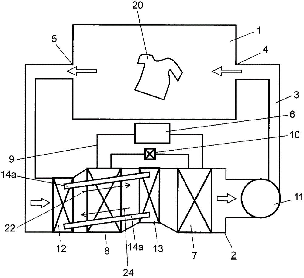
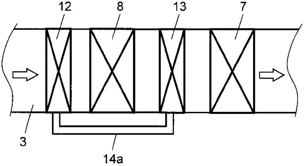
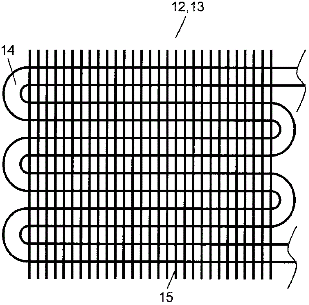
[0022] figure 1 is a schematic view of the drying device according to Embodiment 1 of the present invention as a clothes dryer, figure 2 is a schematic diagram showing the main parts of the heat pump of the drying device, image 3 It is a schematic side view of the upstream side heat exchanger and the downstream side heat exchanger of this drying apparatus.
[0023] exist Figure 1 ~ Figure 3 Among them, the drying chamber 1 accommodates objects to be dried such as clothes 20 . The heat pump 2 is connected to the drying chamber 1 through the circulation air path 3 . Here, the circulating air duct 3 is connected to the drying chamber 1 . The drying chamber 1 is provided with an air supply port 4 for supplying drying air from a circulating air passage 3 and an exhaust port 5 for discharging the drying air. The heat pump 2 has a compressor 6 , an evaporator 8 , a condenser 7 , lines 9 and a pressure reducing valve 10 . Here, the compressor 6 compresses the refrigerant. I...
Embodiment approach 2
[0048] Figure 4 It is a schematic diagram of the drying apparatus in Embodiment 2 of this invention. In Embodiment 2 of the present invention, the same reference numerals are assigned to the same constituent elements as in Embodiment 1, and detailed description thereof will be omitted, and differences will be described.
[0049] In Embodiment 2 of the present invention, a circulation pump 16 is provided on the circulation path of the heat exchange pipe (heat moving part) 14a, and the heat medium is passed through the upstream side heat exchanger 12 and the downstream side heat exchanger 13 by the circulation pump 16. cycle. This point is different from Embodiment 1 of the present invention.
[0050] The circulation pump 16 sucks the heat medium from the lower heat exchange pipe 14 a of the downstream heat exchanger 13 , and pressurizes and sends the heat medium to the lower heat exchange pipe 14 a of the upstream heat exchanger 12 . The circulation pump 16 operates simulta...
Embodiment approach 3
[0056] Figure 5 is a schematic diagram of a drying device according to a third embodiment of the present invention as a clothes dryer, Image 6 is a schematic side view of the heat exchanger on the upstream side of the drying device, Figure 7 It is a schematic side view of the downstream side heat exchanger of this drying apparatus. In Embodiment 3 of the present invention, the same reference numerals are attached to the same components as those in Embodiment 1, detailed description thereof will be omitted, and differences will be described.
[0057] Embodiment 3 of the present invention is different from Embodiment 1 in that a heat pipe 26 is used as a heat transfer unit. That is, the upstream side heat exchanger 12 and the downstream side heat exchanger 13 connected by four heat pipes 26 constituting the heat transfer section are disposed on the left and right adjacent sides of the evaporator 8 in the circulating air duct 3 . The heat pipe (heat transfer portion) 26 is ...
PUM
 Abstract
Description
Claims
Application Information