Stirring paddle and automatic temperature control stirrer using same

The technology of stirring paddle and agitator is applied in the field of automatic temperature control agitator, which can solve the problems of difficult placement of the heated material container, inconvenient operation of the heated material, and lack of automatic stirring function, so as to accelerate the heat transfer speed, The effect of eliminating safety problems and high utilization of heat energy

Inactive Publication Date: 2012-12-05
SHENZHEN POLYTECHNIC
View PDF5 Cites 6 Cited by
  • Summary
  • Abstract
  • Description
  • Claims
  • Application Information

AI Technical Summary

Problems solved by technology

Electric heating tubes mostly use immersion heating, which not only consumes a lot of power, but also has low utilization rate of electric energy. It will also generate waste heat to increase the temperature of the heating medium, making it difficult to accurately control the temperature
[0004] In addition, the above-mentioned water bath or oil bath heating device only has a heating function and does not have an automatic stirring function. During the heating process, it often only relies on the natural diffusion of the temperature of the heating medium, which may easily cause uneven temperature conduction.
Some operators set up stirring paddles during use, and some add a small stirrer or a small paddle to stir or stir locally, so the temperature cannot be accurately controlled.
And the motor directly drives the stirring shaft of the stirring paddle to move. The stirring shaft is located in the center of the water bath or oil bath container.

Method used


Image

  • Stirring paddle and automatic temperature control stirrer using same
  • Stirring paddle and automatic temperature control stirrer using same
  • Stirring paddle and automatic temperature control stirrer using same

Examples


Embodiment Construction

[0033] In order to make the object, technical solution and advantages of the present invention clearer, the present invention will be further described in detail below in conjunction with the accompanying drawings and embodiments. It should be understood that the specific embodiments described here are only used to explain the present invention, not to limit the present invention.

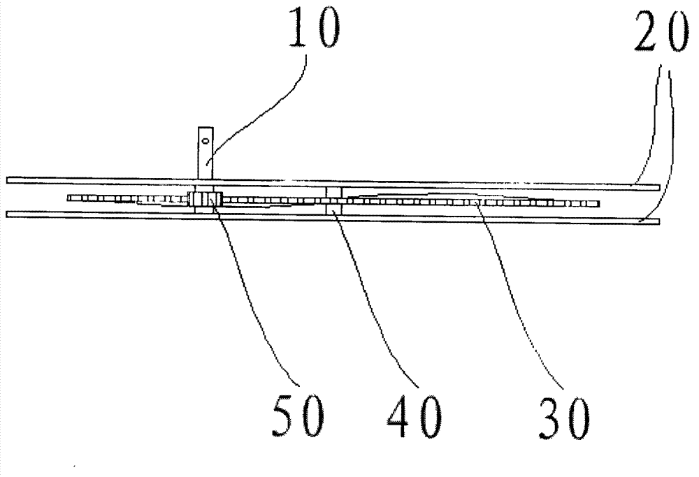
[0034] Such as Figure 1-Figure 2 As shown, the present invention discloses a stirring paddle 300 , including a stirring shaft 10 , a paddle set 30 and a fixing frame for the paddle set 30 .

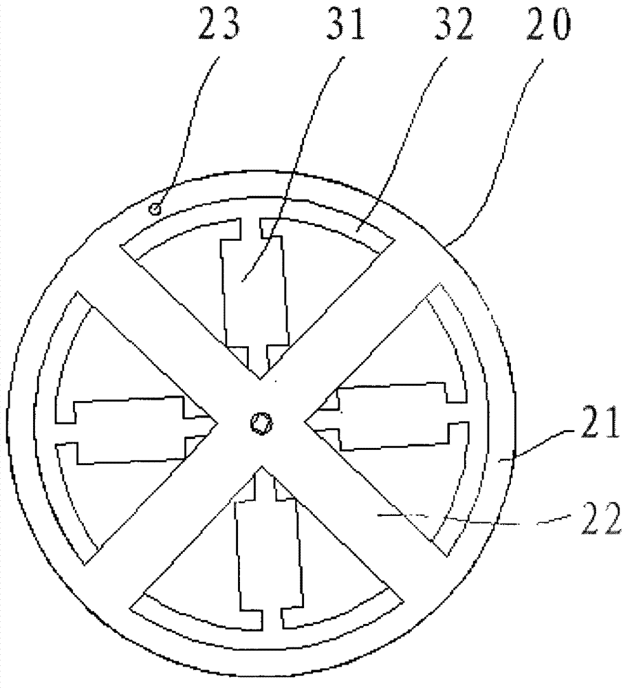
[0035] The paddle set 30 fixing frame includes two upper and lower same hollow fixed plates 20, the fixed plate 20 includes a ring plate 21 and a cross-shaped frame plate 22 located in the ring plate 21 and connected to the ring plate 21, and the ring plate 21 The outer diameter of the outer circle is slightly greater than the sum of the diameters of the addendum circles of the gear plate 32 and the gear 50 ...


PUM


Abstract

The invention discloses a stirring paddle and an automatic temperature control stirrer using same. The stirring paddle comprises a stirring shaft, a paddle group and a paddle group fixing frame, wherein the paddle group fixing frame is fixed together with the middle part of the paddle group; and the stirring shaft runs through the edge of the paddle group fixing frame to be connected with the paddle group through a gear transmission mode. The paddle group fixing frame comprises an upper hollow-out fixed plate and a lower hollow-out fixed plate, which are the same as each other; and the paddle group is fixed between the upper fixed plate and the lower fixed plate. Through the adoption of gear transmission connection, constant instantaneous transmission ratio can be guaranteed, high stability is achieved and accurate and reliable transmission is achieved. As the stirring shaft is biased from the center, the stirring paddle disclosed by the invention is beneficial for containers to accommodate heated materials and convenient for operators to do relevant operations so as to eliminate safety problems. The automatic temperature control stirrer using the stirring paddle has an automatic stirring function, so that the temperature of a heating medium is uniform and heat transfer speed is increased, so that uniformity of heat conducted to the heated materials is guaranteed.

Description

technical field [0001] The invention relates to a water bath or oil bath heating device, in particular to a stirring paddle and an automatic temperature control stirrer using the paddle. Background technique [0002] In the production process of medical and health, light industry food, petrochemical, bioengineering, life science, physical and chemical testing, analysis, synthesis and other production enterprises, as well as in the laboratories of universities and colleges, scientific research units for material temperature control heating experiments or During research, it is often necessary to use a water bath or oil bath heating device to heat the substance. [0003] Traditional water bath or oil bath heating devices mostly use electric heating tubes as heat sources and use thermometers to measure temperature. Electric heating tubes mostly use immersion heating, which not only consumes a lot of power, but also has low utilization rate of electric energy. Waste heat will ...

Claims


Application Information

Patent Timeline
Patent Type & Authority Applications(China)
IPC IPC(8): B01F15/00B01F15/06B01F7/18
Inventor 臧海山
Owner SHENZHEN POLYTECHNIC
Why Eureka
Try Eureka