
Rear retaining device of thin plate shearing machine

A shearing machine and material supporting technology, which is applied in the direction of shearing devices, shearing machine accessories, metal processing equipment, etc., can solve problems such as the inability to achieve horizontal material support, uneven support brackets, and sagging of sheets.

Active Publication Date: 2012-12-05
江苏扬力液压装备有限公司
View PDF10 Cites 18 Cited by
  • Summary
  • Abstract
  • Description
  • Claims
  • Application Information

AI Technical Summary

Problems solved by technology

[0005] 1. The supporting bracket rotates around the rotating shaft at a fixed axis during the loading and unloading process. Due to the limitation of the height of the worktable, the length of the supporting bracket is relatively short. The height of the working table is about 820mm, so the horizontal length of the supporting bracket No more than 500mm, otherwise, after turning, the end of the support bracket away from the workbench has touched the base, and the end of the support bracket close to the workbench is still not lower than the sliding plate, and the horizontal support length of the support bracket is too short to meet the requirements of many users. Require
In order to lengthen the horizontal support length of the support bracket, the height of the workbench must be raised, which not only increases the weight and cost, but is also inconvenient to operate
[0006] 2. Each support bracket is fixed on the rotating shaft by screws. During repeated rotation, it is easy to cause the support bracket to loosen, and there are uneven levels between the support brackets, making it impossible to achieve horizontal support.
[0007] 3. The bottom of the cylinder body of the cylinder is hinged to the lower part of the vertical plate of the workbench, and the bearing seat of the rotating shaft is fixed in the middle of the height direction of the vertical plate of the workbench. The hinge point of the material bracket is also relatively close to the rotating shaft, so that the effective support force generated by the cylinder during the lifting process is very small, especially when cutting a 6mm sheet, it is easy to cause the sheet to sag and cannot achieve horizontal support. The role of material sizing
[0008] 4. The upper plane of the supporting bracket rises to a horizontal position around the rotating shaft or falls below the slope of the sliding plate. The rotation angle is very large, often up to 73 degrees. The stroke of the cylinder is relatively large, and the piston rod is easily deformed, which seriously affects the use of the cylinder. life
[0009] 5. The cut sheet slides down along the upper plane of the support bracket, which is likely to cause scratches on the surface of the sheet, and the length of the support is relatively short, and the sliding distance along the sliding plate is relatively long, which is more likely to cause scratches on the surface of the sheet. scratch

Method used


Image

  • Rear retaining device of thin plate shearing machine
  • Rear retaining device of thin plate shearing machine
  • Rear retaining device of thin plate shearing machine

Examples


Embodiment Construction

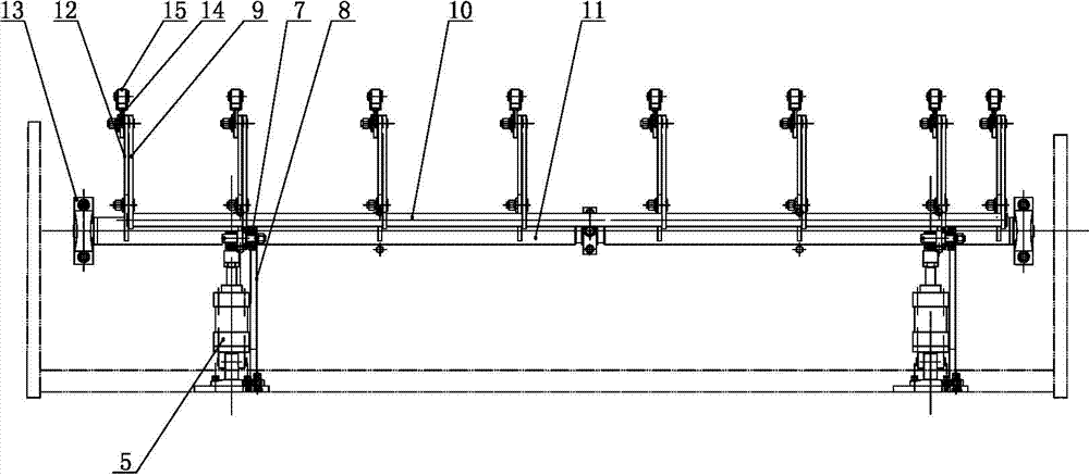
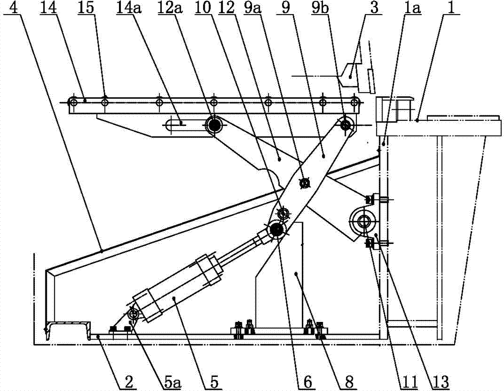
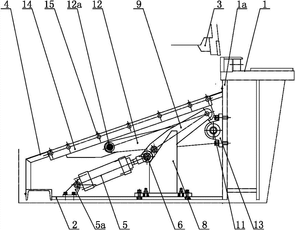
[0021] like figure 1 , figure 2 and image 3 As shown, the rear supporting device of the thin plate shearing machine of the present invention includes a workbench 1, a base 2, a knife rest 3, a supporting bracket 14, a slide plate 4, a cylinder 5, a bearing seat 13 and a rotating shaft 11, and a knife rest 3 Located above the workbench 1, there is a workbench vertical plate 1a in front of the workbench 1, the base 2 extends horizontally forward along the bottom of the workbench vertical plate 1a, and two cylinders 5 are arranged symmetrically along the width direction of the workbench. The rotating shaft 11 extends along the width direction of the vertical plate of the workbench, and the two ends are supported on the bearing seat 13, the bearing seat 13 is fixed in the middle of the height direction of the vertical plate of the workbench, and the slide plates 4 are separated on both sides in the width direction of the front of the workbench And stand in parallel, the upper ...


PUM


Abstract

The invention relates to a rear retaining device of a thin plate shearing machine, wherein cylinders are connected with a foundation in a hinge way; a guide plate is located between each cylinder and an upright plate of a worktable; the top part of a piston rod of each cylinder is connected with a lower roller wheel pin shaft perpendicular to the piston rod in the hinge way; a lower roller wheel is installed on one end of the lower roller wheel pin shaft; the lower roller wheel leans against an inclined plane of the guide plate; one end of the inclined plane of the guide plate far from the worktable inclines downward; the lower roller wheel pin shaft is also connected with connecting rods in the hinge way; the upper parts of the connecting rods are hinged with the lower parts of the rear parts of retaining supports respectively in the hinge way through pins on the connecting rods; multiple rocker arms are evenly welded on a rotary shaft along the axial direction; the middle part of each rocker arm and the middle part of the corresponding connecting rod are hinged onto a center pin of the connecting rod together; the front part and the lower part of each retaining support are provided with a waist-shaped elongated slot parallel with the upper plane of the corresponding retaining bracket respectively; the free end of each rocker arm is connected with a rocker arm pin shaft; and each rocker arm pin shaft is clamped in one waist-shaped elongated slot and further can slide along the waist-shaped elongated slot. With the adoption of the rear retaining device of the thin plate shearing machine, the retaining length is great, the support force is strong and the action is reliable.

Description

technical field [0001] The invention relates to a thin plate shearing machine, in particular to a rear material supporting device of the thin plate shearing machine. Background technique [0002] The rear supporting device of the existing thin plate shearing machine includes a cylinder, a bearing seat, a rotating shaft, a workbench, a knife rest, a support bracket, a sliding plate, etc., the knife rest is located above the workbench, and the bottom of the cylinder body of the cylinder is hinged on the workbench The lower part of the vertical plate, the piston rod of the cylinder is hinged with the lower part of a supporting bracket, and the lower ends of each supporting bracket are respectively fixed on the rotating shaft by screws. The rotating shaft is a steel pipe shaft installed along the width direction of the workbench. The end is supported on the bearing seat, and the bearing seat is fixed in the middle of the height direction of the vertical plate of the workbench. T...

Claims


Application Information

Patent Timeline
Patent Type & Authority Applications(China)
IPC IPC(8): B23D33/02
Inventor 潘世宏朱道泉杨勇常静
Owner 江苏扬力液压装备有限公司
Learn More