Cutter cabinet

A technology for tool cabinets and knives, applied in the field of tool cabinets, can solve problems such as tool cabinet overturning, center of gravity offset, and knives colliding with each other, and achieve the effect of safe and convenient use and simple structure

Inactive Publication Date: 2012-12-05
WUXI INST OF COMMERCE
View PDF5 Cites 5 Cited by
  • Summary
  • Abstract
  • Description
  • Claims
  • Application Information

AI Technical Summary

Problems solved by technology

How to place a wide variety of knives for easy access and avoiding the collision of the knives is a common problem in machining production, especially when the drawer containing the knives is pulled out, the weight of the knives often causes the center of gravity to shift and the knives Cabinet overturned

Method used


Image

  • Cutter cabinet
  • Cutter cabinet
  • Cutter cabinet

Examples


Embodiment Construction

[0014] The present invention will be described in detail below in conjunction with specific embodiments.

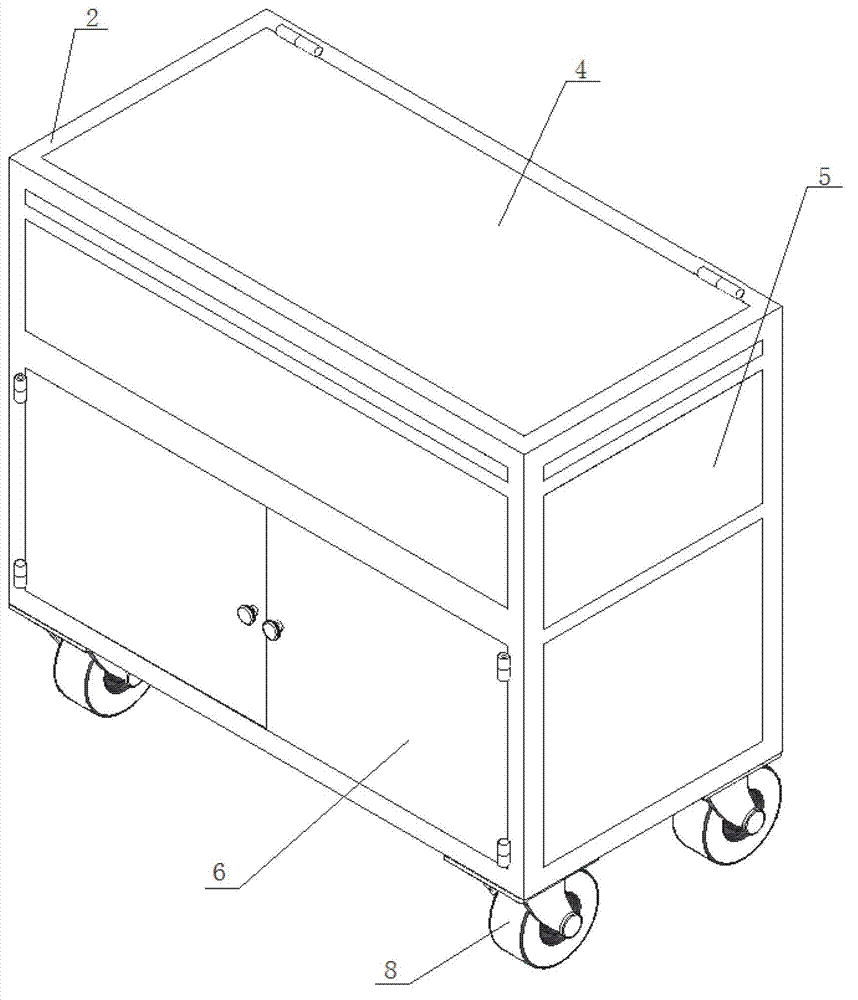
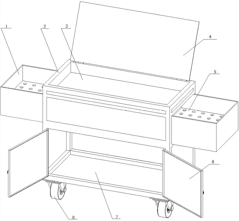
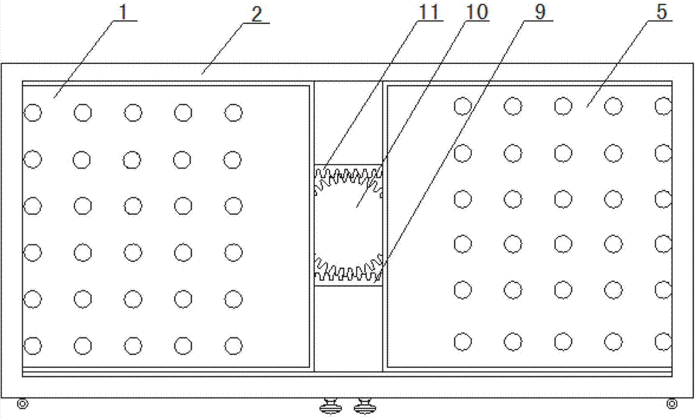
[0015] Such as figure 1 , figure 2 , image 3 and Figure 4 As shown, a tool cabinet for machining machine tools includes a rectangular parallelepiped cabinet body 2, and tool drawers 1 and 5 with toothed racks that can protrude to both sides for storing tools are provided in the middle of the cabinet body, and the tool drawers 1 and 5 There are holes that match the handle of the tool to facilitate the fixing of the tool. The tool drawers 1, 5 are movable to both sides in the guide rails. A cylindrical spur gear 10 is fixed by a bearing in the middle of the cabinet body 2, and the cylindrical spur gear 10 meshes with the racks of the tool drawers 1,5. When pulling the tool drawer 1, 5 to one side, the rack on the drawer drives the cylindrical spur gear 10 to rotate, and the cylindrical spur gear 10 drives the rack on the tool drawer on the other side to move simulta...


PUM


Abstract

The invention discloses a cutter cabinet which comprises a cabinet body, wherein cutter drawers are arranged at the middle part of the cabinet body, the cutter drawers are internally provided with holes matched with cutter handles, the middle of the cabinet body is fixed with a cylindrical straight gear through a bearing, and the cylindrical straight gear is mutually meshed with racks of the cutter drawers. According to the cutter cabinet, when the cutter drawer at one side is pulled, the rack on the cutter drawer can drive the cylindrical straight gear to rotate, simultaneously, the cylindrical straight gear drives the rack on the cutter drawer at the other side to move, so that the cutter drawer at the other side can be pulled to the opposite direction, thereby avoiding the condition that when the cutter drawer at one side is individually pulled out, the cutter cabinet is turned on the side due to the weight of cutters.

Description

technical field [0001] The invention relates to a tool cabinet, in particular to a tool cabinet for machining machine tools. Background technique [0002] Usually machining machine tools need to be equipped with a variety of different processing tools. These knives are heavier and more numerous. How to place a wide variety of knives for easy access and avoiding the collision of the knives is a common problem in machining production, especially when the drawer containing the knives is pulled out, the weight of the knives often causes the center of gravity to shift and the knives Cabinet tipped over. Contents of the invention [0003] In order to solve the above problems, the present invention provides a tool cabinet of a machining machine tool which has a simple structure and can accommodate various special processing tools. [0004] To achieve the above object, the technical solution of the present invention is: [0005] The utility model relates to a knife cabinet, wh...

Claims


Application Information

Patent Timeline
Patent Type & Authority Applications(China)
IPC IPC(8): B23Q13/00
Inventor 高尔军
Owner WUXI INST OF COMMERCE
Why Eureka
Try Eureka