Die for integrally forming I-shaped reinforcement composite material wall plate

An integral molding, composite material technology, applied in the field of resin matrix composite material molding, can solve the problems of increasing tooling cost, profile deviation assembly coordination, increasing material and process cost, etc., and achieves the effect of solving the problem of insufficient pressure.

Active Publication Date: 2012-12-05
AVIC COMPOSITES
View PDF5 Cites 17 Cited by
  • Summary
  • Abstract
  • Description
  • Claims
  • Application Information

AI Technical Summary

Problems solved by technology

In order to solve the assembly coordination problem caused by surface deviation, the method of secondary compensation is usually adopted, that is, after the parts are formed, the exter

Method used


Image

  • Die for integrally forming I-shaped reinforcement composite material wall plate
  • Die for integrally forming I-shaped reinforcement composite material wall plate
  • Die for integrally forming I-shaped reinforcement composite material wall plate

Examples


Embodiment 1

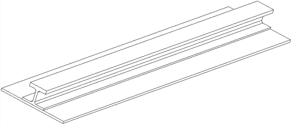
[0032] Embodiment 1: a typical structure such as figure 1 , there is a "work" type reinforcement on the outer skin 7, the overall size is 900mm x 300mm x 50mm (length x width x height), the material is U3160 / QY9512, and the "work" type reinforcement is under the suture technology. The flanges are stitched to the skin and then integrally formed by the RFI process. The surface accuracy of the "I" type reinforced upper flange is required to reach ±0.12mm. We have adopted the solution of the present invention.

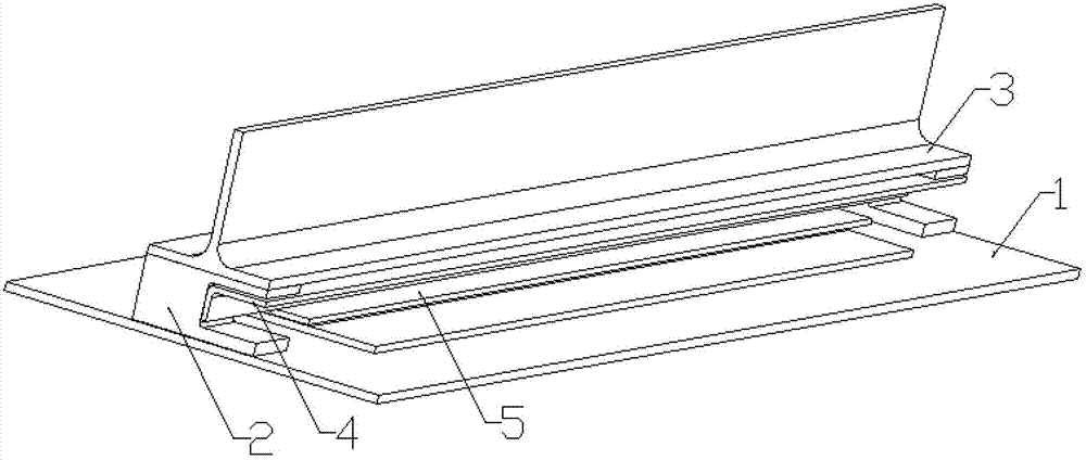
[0033] (a) Design the shape mold 1 according to the shape of the reinforced wall plate, widen 50mm on one side in the horizontal direction, and lengthen 100mm in one side in the vertical direction.

[0034](b) The beam 3 is designed on the outer surface of the reinforced upper flange, and the beam is designed as a "T"-shaped cross-section with better rigidity. Based on the requirements, the profile deviation is not greater than ±0.1mm. The edge of the 3-shaped surface ...

Embodiment 2

[0041] Example 2: The structure of the "I" type reinforced wall plate test piece is as follows Figure 6 , the material is G0827 / QY9512, which is integrally formed by RFI technology. The overall size is 900mm×520mm×105mm (length×width×height), the reinforced wallboard is a wallboard structure with 5 “work” section reinforcements 8 in the longitudinal direction on the skin 7, and the 5 reinforced upper flanges and The metal parts at both ends are required to be assembled with the upper skin. In order to ensure the coordination and consistency of the outer surface 10 of the upper flange of the 5 "work" type ribs and the metal parts at both ends and the inner surface of the upper skin, the 5 "work" The accuracy of the outer surface 10 of the "type reinforced upper flange must be controlled within ±0.2mm. Here we adopt the mold scheme of the present invention, such as Figure 7 shown.

[0042] (a) Considering that the shape of the stiffened plate is flat, the shape mold 1 is des...


PUM

PropertyMeasurementUnit
Lengthaaaaaaaaaa

Abstract

The invention belongs to a technology for forming a resin-base composite material, and relates to a die for integrally forming an I-shaped reinforcement composite material wall plate. The die comprises a contour die 1, positioning blocks 2, cross beams 3, reinforcement forming dies 4, low flange forming dies, and forming auxiliary dies 6. The cross beams 3 and the reinforcement forming dies a4 are positioned by the positioning blocks 2 on the contour die 1, and the upper flange contour surface accuracy and the axis position accuracy are guaranteed by controlling the position accuracy of the assembled cross beams 3 and reinforcement forming dies 4. The die can effectively guarantee the assembly coordination relationship between an upper flange contour surface of the I-shaped reinforcement composite material wall plate and a skin molded surface of the wall plate.

Description

technical field [0001] The invention belongs to the molding technology of resin-based composite materials, and relates to a mold for integrally molding "I" type reinforced composite material wall boards. Background technique [0002] At present, composite materials are used in more and more parts of the aircraft, and the advantages of advanced composite materials such as high specific strength, high specific stiffness and designability are used to reduce structural weight and improve aircraft maneuverability or carrying capacity. [0003] Reinforced panel-type composite components have become a widely used structural form of composite fuselage, wing and vertical tail due to their good stiffness. The commonly used reinforced panels are divided into "T" type reinforced panels, "J" type reinforced panels, "I" type reinforced panels and mixed type reinforced panels according to the different reinforced sections. . The traditional forming method is generally to cure the skin an...

Claims


Application Information

Patent Timeline
IPC IPC(8): B29C33/42
Inventor 高艳秋赵龙
Owner AVIC COMPOSITES
Why Eureka
Try Eureka