Method for inhibiting coking of hydrocarbon cracking furnace tube during on-line coke burning process
A hydrocarbon cracking furnace tube and furnace tube technology, applied in cracking, non-catalytic thermal cracking, petroleum industry, etc., can solve problems such as excessive oxidation, cumbersome steps, uneven coating distribution, etc., to prolong service life and prolong operation Cycle, the effect of reducing the amount of coking
- Summary
- Abstract
- Description
- Claims
- Application Information
AI Technical Summary
Problems solved by technology
Method used
Image
Examples
Embodiment 1
[0029] Using a 2520 nickel-chromium alloy furnace tube with a size of φ14×2×800 on a self-made laboratory device with a feed rate of 200g / h, naphtha was used as a cracking raw material to conduct a pyrolysis coking evaluation test. After the pyrolysis is completed, the air is used for charring, and the CO and CO in the charred gas 2 The concentration is measured online by an infrared instrument, and the volume of the charred gas is recorded online by a wet flow meter. Finally, the amount of carbon in the charred gas is calculated as the amount of coking in the cracking process. The cracking test conditions are as follows:
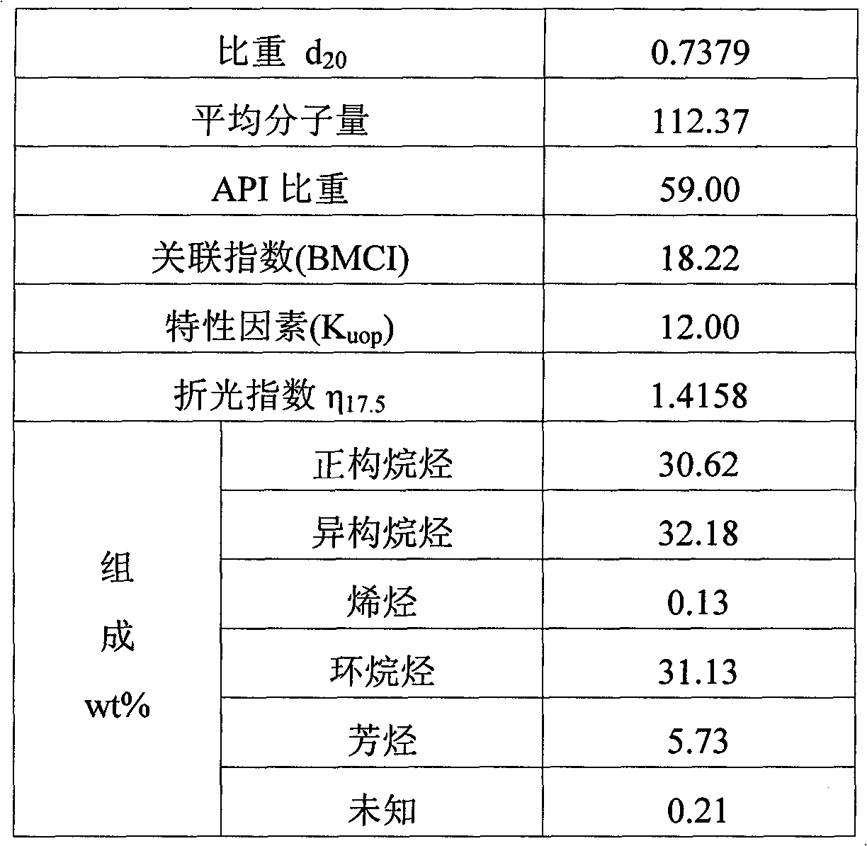
[0030] Raw material: industrial naphtha (see Table 1 for physical properties)
[0031] Table 1 Physical properties of industrial naphtha
[0032]
[0033] Lysis time: 2 hours
[0034] Preheater temperature: 600°C
[0035]Cracking furnace temperature: 850°C
[0036] Water to oil ratio: 0.5
[0037] After the charring is completed, use air as the car...
Embodiment 2
[0049] The 2520 furnace tube of the same material as Example 1 and the same cracking conditions are used for testing. After the charring is completed, nitrogen is used as a carrier gas to bring hexamethyldisiloxane vapor into the furnace tube for vapor deposition. The deposition conditions as follows:
[0050] Furnace tube temperature: 700°C Air flow rate: 0.5L / min
[0051] Deposition time: 6 hours Volume percentage of hexamethyldisiloxane: 3.0%
[0052] The surface composition of the furnace tube before and after vapor deposition, the results are shown in Table 4.
[0053] Element distribution (wt%) on the surface of the furnace tube before and after vapor deposition in Table 4 Example 2
[0054] Chemical composition (wt%)
[0055] It can be seen from Table 4 that SiO is formed on the surface of the vapor deposition furnace tube 2 coating.
[0056] Continue to carry out the cracking and coking evaluation test according to the method described before untreated...
PUM
 Abstract
Description
Claims
Application Information
 - R&D
- Intellectual Property
- Life Sciences
- Materials
- Tech Scout
- Unparalleled Data Quality
- Higher Quality Content
- 60% Fewer Hallucinations
Browse by: Latest US Patents, China's latest patents, Technical Efficacy Thesaurus, Application Domain, Technology Topic, Popular Technical Reports.
© 2025 PatSnap. All rights reserved.Legal|Privacy policy|Modern Slavery Act Transparency Statement|Sitemap|About US| Contact US: help@patsnap.com

